×
ToyotaParts- Hello
- Login or Register
- Quick Links
- Live Chat
- Track Order
- Parts Availability
- RMA
- Help Center
- Contact Us
- Shop for
- Toyota Parts
- Scion Parts
My Garage
My Account
Cart
OEM 2004 Toyota Sequoia Axle Shaft
Car Axle Shaft- Select Vehicle by Model
- Select Vehicle by VIN
Select Vehicle by Model
orMake
Model
Year
Select Vehicle by VIN
For the most accurate results, select vehicle by your VIN (Vehicle Identification Number).
2 Axle Shafts found


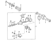
2004 Toyota Sequoia Axle Shaft, Rear
Part Number: 42311-34050$583.38 MSRP: $854.95You Save: $271.57 (32%)Product Specifications- Other Name: Shaft, Rear Axle; Drive Axle Shaft, Rear; Axle Shafts; Shaft, Rear Axle, Passenger Side; Shaft, Rear Axle, Driver Side
- Position: Rear
- Item Weight: 16.10 Pounds
- Item Dimensions: 27.6 x 8.5 x 7.4 inches
- Condition: New
- Fitment Type: Direct Replacement
- SKU: 42311-34050
- Warranty: This genuine part is guaranteed by Toyota's factory warranty.


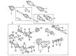
2004 Toyota Sequoia Axle Assembly, Front
Part Number: 43430-0C010$372.28 MSRP: $572.11You Save: $199.83 (35%)Product Specifications- Other Name: Shaft Assembly, Front Drive; CV Axle Assembly, Front Left, Front Right; GSP Cv Axle; Axle Shaft; Shaft Assembly, Front Drive, Passenger Side; Shaft Assembly, Front Drive, Driver Side; CV Axle Assembly
- Position: Front
- Item Weight: 23.70 Pounds
- Item Dimensions: 30.7 x 6.2 x 6.2 inches
- Condition: New
- Fitment Type: Direct Replacement
- SKU: 43430-0C010
- Warranty: This genuine part is guaranteed by Toyota's factory warranty.
2004 Toyota Sequoia Axle Shaft
Looking for affordable OEM 2004 Toyota Sequoia Axle Shaft? Explore our comprehensive catalogue of genuine 2004 Toyota Sequoia Axle Shaft. All our parts are covered by the manufacturer's warranty. Plus, our straightforward return policy and speedy delivery service ensure an unparalleled shopping experience. We look forward to your visit!
2004 Toyota Sequoia Axle Shaft Parts Q&A
- Q: How to Service and Repair an Axle Shaft on 2004 Toyota Sequoia?A: Start axle shaft repairs by removing the bearing retainer at the differential side along with the speed sensor rotor using 4 serration bolts with attached nuts before extracting them from the backing plate with a hammer but never reusing any existing nuts. Apply the grinder to smooth the retainer and sensor rotor faces before extracting them with a chisel while using a hammer. You must utilize a snap ring expander to extract the snap ring which is situated on the axle shaft. The process of removing rear axle shafts requires washers and nuts to be attached to serration bolts followed by nut torque adjustment before using a tool to remove the 4 nuts. Position the Special Service Tool assembly 09521-25011, 09521-25021 onto the backing plate with four nuts and apply a press to extract the rear axle shaft and its spring washer along with bearing retainer from the plate before removing both tools. A brass bar and hammer will assist in extracting the 6 hub bolts and oil deflector while removing the gasket. The inspection process includes measuring the shaft runout using a dial indicator that requires maximum shaft runout below 0.079 inch (2.0 mm) and maximum flange runout below 0.0040 inch (0.1 mm). Replace the damaged rear axle shaft or one with excessive runout values. Use Special Service Tools: 09308-00010 and 09950-60020 (09951-00710) and 09950-70010 (09951-07150) with a hammer to replace the inner oil seal preceded by cleaning the oil seal lip with MP grease. During the reassembly process position the backing plate on the bearing assembly before using a press that requires two socket wrenches to install the serration bolts. Put new gasket pieces along with oil deflectors onto the axle shaft followed by attaching a new hub bolt screw which requires torque application. To install the rear axle shaft begin by positioning the backing plate along with a spring washer and bearing retainer onto the rear axle shaft. The rear axle shaft installation requires the use of Special Service Tool: 09631-12090, 09950-10020 (09951-01030) and a press to accomplish the task. Install a new snap ring with a snap ring expander before inserting the new speed sensor rotor and bearing retainer (differential side) which should be performed with Special Service Tool: 09631-12090, 09950-60020 (09951-01030). The appropriate length for this component should measure 170.7 plus or minus 1.0 mm (6.720 plus or minus 0.039 inch).
Related 2004 Toyota Sequoia Parts
 2004 Toyota Sequoia Coil Springs
 2004 Toyota Sequoia Ball Joint
 2004 Toyota Sequoia CV Boot
 2004 Toyota Sequoia CV Joint
 2004 Toyota Sequoia Differential Mount
 2004 Toyota Sequoia Front Cross-Member
 2004 Toyota Sequoia Shock And Strut Mount
 2004 Toyota Sequoia Steering Knuckle
 2004 Toyota Sequoia Sway Bar Bushing
 2004 Toyota Sequoia Sway Bar Link
 2004 Toyota Sequoia Wheel Cover
 2004 Toyota Sequoia Wheel Seal