×
ToyotaParts- Hello
- Login or Register
- Quick Links
- Live Chat
- Track Order
- Parts Availability
- RMA
- Help Center
- Contact Us
- Shop for
- Toyota Parts
- Scion Parts
My Garage
My Account
Cart
OEM 2004 Toyota Land Cruiser Differential
Front Differential- Select Vehicle by Model
- Select Vehicle by VIN
Select Vehicle by Model
orMake
Model
Year
Select Vehicle by VIN
For the most accurate results, select vehicle by your VIN (Vehicle Identification Number).
4 Differentials found


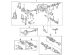
2004 Toyota Land Cruiser Carrier Assembly, Differential, Front
Part Number: 41110-60801$1752.66 MSRP: $2568.54You Save: $815.88 (32%)Ships in 1-3 Business DaysProduct Specifications- Other Name: Carrier Assembly, Differential; Differential
- Manufacturer Note: *FGR=41:10=4.100
- Position: Front
- Part Name Code: 41110F
- Item Weight: 63.00 Pounds
- Item Dimensions: 26.0 x 19.8 x 14.0 inches
- Condition: New
- Fitment Type: Direct Replacement
- SKU: 41110-60801
- Warranty: This genuine part is guaranteed by Toyota's factory warranty.

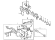
2004 Toyota Land Cruiser Carrier Assembly, Differential
Part Number: 41110-60A21$1819.62 MSRP: $2666.68You Save: $847.06 (32%)Ships in 1-3 Business DaysProduct Specifications- Other Name: CARRIER ASSY, DIFFER; Differential
- Position: Rear
- Replaces: 41110-60A20, 41110-60871
- Item Weight: 69.70 Pounds
- Item Dimensions: 30.8 x 26.9 x 18.4 inches
- Condition: New
- SKU: 41110-60A21
- Warranty: This genuine part is guaranteed by Toyota's factory warranty.

2004 Toyota Land Cruiser Differential Case
Part Number: 41301-60080$376.35 MSRP: $551.55You Save: $175.20 (32%)Ships in 1-3 Business DaysProduct Specifications- Other Name: Case Sub-Assembly, Differential; Case Sub-Assembly, Rear Differential; Differential
- Part Name Code: 41302
- Item Weight: 6.10 Pounds
- Item Dimensions: 6.8 x 6.8 x 6.5 inches
- Condition: New
- Fitment Type: Direct Replacement
- SKU: 41301-60080
- Warranty: This genuine part is guaranteed by Toyota's factory warranty.

2004 Toyota Land Cruiser Differential Case
Part Number: 41302-24010$410.54 MSRP: $601.65You Save: $191.11 (32%)Product Specifications- Other Name: Case Sub-Assembly, Differential; Case Sub-Assembly, Front Differential; Case Sub-Assembly, Rear Differential; Differential
- Manufacturer Note: *AXC=G284
- Item Weight: 5.90 Pounds
- Item Dimensions: 7.2 x 7.1 x 6.4 inches
- Condition: New
- Fitment Type: Direct Replacement
- SKU: 41302-24010
- Warranty: This genuine part is guaranteed by Toyota's factory warranty.
2004 Toyota Land Cruiser Differential
Looking for affordable OEM 2004 Toyota Land Cruiser Differential? Explore our comprehensive catalogue of genuine 2004 Toyota Land Cruiser Differential. All our parts are covered by the manufacturer's warranty. Plus, our straightforward return policy and speedy delivery service ensure an unparalleled shopping experience. We look forward to your visit!
2004 Toyota Land Cruiser Differential Parts Q&A
- Q: How to service and repair the center differential on 2004 Toyota Land Cruiser?A: The service and repair of the center differential starts with measuring the high speed output gear thickness using a dial indicator, a feeler gauge and Special Service Tools. Operate the dial indicator at a 0.10 - 0.25 mm (0.0039 - 0.0098 inch) thrust clearance and 0.035 - 0.091 mm (0.00138 - 0.00358 inch) radial clearance range. Serviceechnicians must use Special Service Tools 09950-00020, 09950-60010 (09951-00320) with a press to remove the front drive gear piece after expanding the snap ring while maintaining the center differential assembly free from drops. Use Special Service Tool: 09950-00020 along with a press to extract the front taper roller bearing which must have its claw firmly attached to the bearing inner race. The removal of the high speed output gear and two needle roller bearings, high and low clutch sleeve, high speed output gear bushing and clutch hub requires Special Service Tools: 09950-00020, 09950-00030, 09950-60010 (09951-00320), and a magnetic finger to extract the straight pin from the differential front case. Use Special Service Tool: 09950-00020, 09950-60010 (09951-00320) with a press to remove the rear taper roller bearing by aligning the claw onto the bearing inner face. Proceed to disassemble the differential rear case and its 12 bolts. Remove the rear side gear along with the pinion shaft and two pinion gears and two thrust washers by properly extracting the straight pin from the pinion shaft. Cautiously strike the low gear using a plastic hammer for removal while preventing any possible damage. When ready to assemble the low gear you must first put gear oil on all surfaces which slide or rotate. You need to clean the differential case contact area before heating the low gear in boiling water then immediately installing it when the water has evaporated. Insert the thrust washer before placing the front side gear followed by the pinion shaft and two pinion gears and thrust washers. Verify the front case backlash using a dial indicator because it should remain below 0.05 mm (0.0020 inch). The thrust washer needs replacement according to specifications when necessary. Take another backlash measurement of the rear case before putting in the straight pin to the pinion shaft together with the rear side gear and thrust washer. After putting in the differential rear case with 12 set bolts you must apply torque at 88 Nm (900 kgf-cm, 65 ft. lbs.) and then rotate the pinion gear before loosening and retorquing the bolts to 98 Nm (1,000 kgf-cm, 72 ft. lbs.). Use Special Service Tool: 09316-12010 together with a press to install the rear taper roller bearing before installing the clutch hub through the combination of Special Service Tool: 09310-12010, 09316-60011 (09316-00011) and press. When installing the straight pin along with the high speed output gear bushing you must use Special Service Tool: 09316-12010, 09310-60011 (09316-00011) with a press to apply MP grease and position the bushing groove correctly with respect to the shaft pin. The high and low clutch sleeve needs to be placed correctly before applying gear oil to the needle roller bearing so installation of the high speed output gear can proceed. Utilize the front taper roller bearing Special Service Tools: 09316-12010, 09316-60011 (09316-00011) and a press for installation followed by the front drive gear piece with the same tools and press system for installation, then use a snap ring expander tool to install a new ring selecting an appropriate size for minimum axial play. Estimate the radial and thrust clearance of the high speed output gear through final inspection.
Related 2004 Toyota Land Cruiser Parts
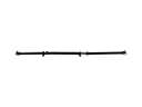 2004 Toyota Land Cruiser Drive Shaft
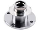 2004 Toyota Land Cruiser CV Joint Companion Flange
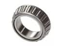 2004 Toyota Land Cruiser Differential Bearing
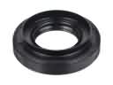 2004 Toyota Land Cruiser Differential Seal
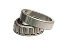 2004 Toyota Land Cruiser Pinion Bearing
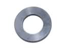 2004 Toyota Land Cruiser Pinion Washer
 2004 Toyota Land Cruiser Slip Yoke
 2004 Toyota Land Cruiser Transfer Case Bearing
 2004 Toyota Land Cruiser Transfer Case Seal
 2004 Toyota Land Cruiser Universal Joint