×
ToyotaParts- Hello
- Login or Register
- Quick Links
- Live Chat
- Track Order
- Parts Availability
- RMA
- Help Center
- Contact Us
- Shop for
- Toyota Parts
- Scion Parts
My Garage
My Account
Cart
OEM 2004 Toyota 4Runner Camshaft
Cam- Select Vehicle by Model
- Select Vehicle by VIN
Select Vehicle by Model
orMake
Model
Year
Select Vehicle by VIN
For the most accurate results, select vehicle by your VIN (Vehicle Identification Number).
8 Camshafts found


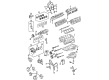
2004 Toyota 4Runner Camshaft
Part Number: 13501-31040$547.97 MSRP: $803.06You Save: $255.09 (32%)Ships in 1-3 Business DaysProduct Specifications- Other Name: Camshaft Sub-Assembly
- Part Name Code: 13511
- Item Weight: 4.30 Pounds
- Item Dimensions: 22.4 x 3.5 x 2.9 inches
- Condition: New
- Fitment Type: Direct Replacement
- SKU: 13501-31040
- Warranty: This genuine part is guaranteed by Toyota's factory warranty.

2004 Toyota 4Runner Camshaft
Part Number: 13502-31010$547.97 MSRP: $803.06You Save: $255.09 (32%)Ships in 1-3 Business DaysProduct Specifications- Other Name: Camshaft Sub-Assembly
- Part Name Code: 13512
- Item Weight: 4.40 Pounds
- Item Dimensions: 22.4 x 3.4 x 2.9 inches
- Condition: New
- Fitment Type: Direct Replacement
- SKU: 13502-31010
- Warranty: This genuine part is guaranteed by Toyota's factory warranty.

2004 Toyota 4Runner Camshaft
Part Number: 13054-31010$547.97 MSRP: $803.06You Save: $255.09 (32%)Ships in 1-3 Business DaysProduct Specifications- Other Name: Camshaft Sub-Assembly
- Part Name Code: 13054
- Item Weight: 4.90 Pounds
- Item Dimensions: 22.0 x 3.4 x 2.9 inches
- Condition: New
- Fitment Type: Direct Replacement
- SKU: 13054-31010
- Warranty: This genuine part is guaranteed by Toyota's factory warranty.

2004 Toyota 4Runner Camshaft
Part Number: 13053-31010$547.97 MSRP: $803.06You Save: $255.09 (32%)Ships in 1-3 Business DaysProduct Specifications- Other Name: Camshaft Sub-Assembly
- Part Name Code: 13053
- Item Weight: 4.80 Pounds
- Item Dimensions: 21.4 x 3.5 x 3.0 inches
- Condition: New
- Fitment Type: Direct Replacement
- SKU: 13053-31010
- Warranty: This genuine part is guaranteed by Toyota's factory warranty.
2004 Toyota 4Runner Camshaft
Part Number: 13501-50050$496.21 MSRP: $727.20You Save: $230.99 (32%)Ships in 1-3 Business DaysProduct Specifications- Other Name: Camshaft Sub-Assembly, Intake
- Manufacturer Note: (J)
- Part Name Code: 13511
- Item Weight: 6.30 Pounds
- Item Dimensions: 21.3 x 3.3 x 2.9 inches
- Condition: New
- Fitment Type: Direct Replacement
- SKU: 13501-50050
- Warranty: This genuine part is guaranteed by Toyota's factory warranty.
- Product Specifications
- Other Name: Camshaft Sub-Assembly, Exhaust
- Manufacturer Note: (J)
- Part Name Code: 13512
- Item Weight: 4.20 Pounds
- Item Dimensions: 22.2 x 3.3 x 3.0 inches
- Condition: New
- Fitment Type: Direct Replacement
- SKU: 13502-50030
- Warranty: This genuine part is guaranteed by Toyota's factory warranty.
- Product Specifications
- Other Name: Camshaft Sub-Assembly, Exhaust; Camshaft Sub-Assembly
- Manufacturer Note: (J)
- Part Name Code: 13054
- Item Weight: 4.60 Pounds
- Item Dimensions: 21.4 x 3.5 x 2.9 inches
- Condition: New
- Fitment Type: Direct Replacement
- SKU: 13054-50030
- Warranty: This genuine part is guaranteed by Toyota's factory warranty.
- Product Specifications
- Other Name: Camshaft Sub-Assembly, I; Camshaft Sub-Assembly
- Manufacturer Note: (J)
- Part Name Code: 13053
- Item Weight: 15.60 Pounds
- Item Dimensions: 21.0 x 3.5 x 2.9 inches
- Condition: New
- Fitment Type: Direct Replacement
- SKU: 13053-50050
- Warranty: This genuine part is guaranteed by Toyota's factory warranty.
2004 Toyota 4Runner Camshaft
Looking for affordable OEM 2004 Toyota 4Runner Camshaft? Explore our comprehensive catalogue of genuine 2004 Toyota 4Runner Camshaft. All our parts are covered by the manufacturer's warranty. Plus, our straightforward return policy and speedy delivery service ensure an unparalleled shopping experience. We look forward to your visit!
2004 Toyota 4Runner Camshaft Parts Q&A
- Q: How to replace the camshaft (RH) on 2004 Toyota 4Runner?A: To replace the camshaft (RH), begin by draining the engine coolant and removing the V-bank cover, followed by disconnecting ventilation hose No.2, removing the air cleaner assembly, and taking out the intake air surge tank by disconnecting the two water by-pass hoses, fuel vapor feed hose, ventilation hose, two VSV connectors, and throttle body w/motor connector, then separating the three wire harness clamps and hose clamp, removing the two bolts and throttle body bracket, the bolt and oil baffle plate, the four bolts and two surge tank stays, and the two nuts, before using a socket hexagon wrench 8 to remove the four bolts, intake air surge tank, and gasket. The technician removes the ignition coil assembly and the cylinder head cover sub-assembly through bolting out ten bolts, three seal washers, two nuts, and cylinder head cover and gasket before repeating the procedure for the LH sub-assembly. Insert the crankshaft pulley notch into timing mark "0" on the timing chain cover for proper alignment of camshaft timing gear marks with the bearing cap's marks. Turn the crankshaft fully and realign it to record which No.1 chain links match the timing marks. The procedure requires you to remove Chain Tensioner Assembly No.1 while maintaining crankshaft stability, followed by reading the camshaft with the timing chain detached by first turning the crankshaft counterclockwise 40 degrees from TDC position. After removing four bolts and a timing chain cover plate with gasket, push the chain tensioner plunger in while implementing upward stopper plate rotation which can be secured with a 3.5 mm bar before extracting the two bolts and tensioner assembly. For No.2 camshaft removal, keep it level to avoid damage, raise chain tensioner No. 2, insert a 1.0 mm pin to fix it, hold the hexagonal portion of the No. 2 camshaft with a wrench, and remove the camshaft timing gear set bolt, separating the timing gear from the No. 2 camshaft, rotating it counterclockwise until the cam lobes of No. 1 cylinder face upward, then uniformly loosen and remove the eight bearing cap bolts in the specified sequence, followed by removing the four bearing caps and No. 2 camshaft. The chain tensioner assembly No. 2 can be removed after the bolt is taken out then the assembly is released. Start by leveling the No.1 camshaft before using a wrench to grip its hexagonal part and then loosening the timing gear set bolt and sliding the timing gear to expose cam lobes pointing downward after loosening bearing cap bolts per sequence for eight holes, finally lifting the camshaft with bolt removal and string-based No.1 chain securing. To install the camshaft, align the mark link with the timing mark of the camshaft timing gear, apply new engine oil to the thrust portion and journal, temporarily put the No. 1 chain on the No. 2 chain, align the knock pin hole with the knock pin of the No. 1 camshaft, insert it into the timing gear, temporarily install the timing gear set bolt, set the No. 1 camshaft onto the RH cylinder head with the cam lobes facing downward, install the four bearing caps, apply engine oil to the threads and under the heads of the bearing cap bolts, and tighten the eight bolts uniformly in the specified sequence with the given torque specifications. Tighten the timing gear set bolt to its specified torque while holding the hexagonal portion with a wrench and aligning the paint mark of the No. 1 chain with the timing mark and the camshaft timing mark with the bearing cap. The installation of chain tensioner assembly No. 2 requires tensioning the unit followed by a 1.0 mm pin insertion. Then temporarily install the timing gear and tensioner then align the mark links at their correct positions before torquing the tensioner bolt to its specified value. Prior to putting in the No.2 camshaft it should be placed on the RH cylinder head with upward cam lobe orientation and procedure should follow bearing cap installation then engine oil application to threading and bolt heads followed by eight bolt uniform torque tightening according to specified sequence before rotating the camshaft counterclockwise to position knock pin alignment and hexagonal portion wrench holding to install timing gear set bolt to specified torque while removing pin from chain tensioner No. 2. The procedure for assembly of chain tensioner No.1 involves pushing in the plunger through stopper plate rotation followed by holding with a 3.5 mm bar installation of two bolts at specified torque then bar removal and new gasket along with timing chain cover plate installation with four bolts tightened to specified torque followed by crankshaft pulley rotation two complete revolutions and examination of timing marks alignment. Begin with No. 1 cylinder set at TDC/compression position then inspect and adjust valve clearance before installing the LH cylinder head cover sub-assembly by using Part No. 08826-00080 or equivalent seal packing while installing seal washers followed by tightnning bolts and nuts to specified torque values before repeating this process for the RH side. After torqueing the ignition coil assembly at its specified level come next the installation of the intake air surge tank with new gasket under the guidance of a socket hexagon wrench 8 and its four bolts tightened to specified torque succeeding installation of two nuts and two surge tank stays with specified torque then install oil baffle plate with specified torque followed by throttle body bracket installation with two bolts torqued to specified level and final execution of all hoses and connectors. The last step includes attaching the air cleaner assembly then connecting ventilation hose No.2 while adding engine coolant then searching for leaks before attaching the two nuts to the specified torque on the V-bank cover. Special Service Tool: 09843 - 18040 is needed to check the ignition timing.
Related 2004 Toyota 4Runner Parts
 2004 Toyota 4Runner Oil Filter
 2004 Toyota 4Runner Timing Chain
 2004 Toyota 4Runner Crankshaft Gear
 2004 Toyota 4Runner Crankshaft Pulley
 2004 Toyota 4Runner Crankshaft Thrust Washer Set
 2004 Toyota 4Runner Dipstick
 2004 Toyota 4Runner Dipstick Tube
 2004 Toyota 4Runner Drain Plug Washer
 2004 Toyota 4Runner Engine Mount
 2004 Toyota 4Runner Piston
 2004 Toyota 4Runner Valve Stem Seal
 2004 Toyota 4Runner Variable Timing Sprocket