×
ToyotaParts- Hello
- Login or Register
- Quick Links
- Live Chat
- Track Order
- Parts Availability
- RMA
- Help Center
- Contact Us
- Shop for
- Toyota Parts
- Scion Parts
My Garage
My Account
Cart
OEM 2004 Scion xA Rack And Pinion
Steering Rack And Pinion- Select Vehicle by Model
- Select Vehicle by VIN
Select Vehicle by Model
orMake
Model
Year
Select Vehicle by VIN
For the most accurate results, select vehicle by your VIN (Vehicle Identification Number).
1 Rack And Pinion found

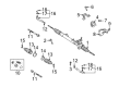
2004 Scion xA Steering Gear
Part Number: 44200-52340$610.09 MSRP: $894.08You Save: $283.99 (32%)Ships in 1-3 Business DaysProduct Specifications- Other Name: Rack and Pinion Assembly; Steering Gearbox; Gear Assembly; Steering Gear Assembly; Link Assembly, Power Steering
- Part Name Code: 44200
- Item Weight: 13.70 Pounds
- Item Dimensions: 50.2 x 10.4 x 6.6 inches
- Condition: New
- Fitment Type: Direct Replacement
- SKU: 44200-52340
- Warranty: This genuine part is guaranteed by Toyota's factory warranty.
2004 Scion xA Rack And Pinion
Looking for affordable OEM 2004 Scion xA Rack And Pinion? Explore our comprehensive catalogue of genuine 2004 Scion xA Rack And Pinion. All our parts are covered by the manufacturer's warranty. Plus, our straightforward return policy and speedy delivery service ensure an unparalleled shopping experience. We look forward to your visit!
2004 Scion xA Rack And Pinion Parts Q&A
- Q: How to Overhaul a Power Steering Rack and Pinion Assembly on 2004 Scion xA?A: Begin the power steering link assembly overhaul by installing Special Service Tool: 09631-10041 to the rack and pinion and smoothing the rack and pinion teeth end if necessary and applying power steering fluid to the tool before installing the rack and pinion to the rack housing and removing the tool. Install the rack bush oil seal by using Special Service Tools: 09950-60010 (09951-00210, 09951-00340, 09952-06010) and 09950-70010 (09951-07100) with a press to complete the job. Proper oil seal installation should be followed by applying power steering fluid on a new O-ring and then covering the rack and pinion end with vinyl tape to protect the oil seal lip before placing the rack bush into the rack housing. Place the cylinder end stopper before setting the hole snap ring with needle nose pliers. The Special Service Tool: 09631-12071 (09633-00010) must be installed on the rack housing while applying a vacuum of 53 kPa (400 mm Hg, 15.75 inch Hg) for 30 seconds to check the vacuum pressure and repair oil seals if leaks are found. First apply grease to the needle roller bearing followed by rack housing gasket installation. Then align the matchmarks before mounting the control valve housing equipped with control valve onto the rack housing by using 2 bolts constricted to 21 Nm (214 kgf-cm, 15 ft. lbs.). Perform the following steps for installing the rack guide assembly: Install the rack guide along with the rack guide spring spacer and rack guide spring but keep the rack guide spring cap only temporarily in place. Apply Part No. 08833-00080 Three Bond 1344 Loctite 242 or equivalent sealant onto 2 or 3 threads of the rack guide spring cap. The rack end sub-assy should be installed temporarily to adjust total preload by torquing the rack guide spring cap to 25 Nm (250 kgf-cm, 18 ft. lbs.) using a hexagon wrench (19 mm) before returning the cap approximately 12 degrees for control valve adjustment using Special Service Tool: 09616-00110. Install the rack guide spring cap while using Special Service Tool: 09616-00011 and a torque wrench along with hexagon wrench (19 mm) to tighten until the preload reaches 1.2 to 1.5 Nm (12 to 15 kgf-cm, 10.6 to 13.3 inch lbs.). Apply sealant to the spring cap lock nut threads before temporarily installing it. The hexagon wrench (19mm) should be used to hold the rack guide spring cap so users can torque the spring cap locknut to 28 Nm (286 kgf-cm or 21 ft. lbs.) using Special Service Tool: 09922-10010. Users must check preload one more time. The service tech should first remove both rack ends sub-assembly and then reinstall temporary sub-assembly parts before applying 60 Nm torque to the assembled units using Special Service Tool: 09922-10010. The technician must clear any clogs from the rack and pinion end hole before applying silicon grease to rack boot No.2's inner small caliber. The boot should be installed onto the rack housing correctly without damaging or twisting its shape. Apply Special Service Tool: 09240-00020, 09521-24010 to adjust the rack boot No.2 clamp until the clearance reaches 3.0 mm (0.118 inch) before repeating the procedure for rack boot No.1 clamp. The repair process requires installation of the 2 rack boot clips followed by tightening the lock nut with the tie rod end sub-assy LH onto the rack end sub-assy while matching mark positions and torquing to 74 Nm (750 kgf-cm, 54 ft. lbs.) before repeating the procedure for the RH side. Use power steering fluid to lubricate the 2 new O-rings before their installation onto the right turn pressure tube. Then, install the tube with Special Service Tool: 09023-38200 while applying parallel torque force of 12 Nm (118 kgf-cm, 9 ft. lbs.) to the tool. A necessary procedure includes installing grommet No.2 to the power steering link assy following bracket No.2 installation symmetrically with the inscribed mark facing forward while tightening the assembly with 4 bolts and nuts to 74 Nm (749 kgf-cm, 54 ft. lbs.). Fit the steering intermediate shaft to its proper alignment through matchmarks then fasten the bolt to 28 Nm (290 kgf-cm, 21 ft. lbs.). Secure the power steering rack housing heat insulator by torquing its bolt to 18 Nm (178 kgf-cm, 13 ft. lbs.) and its additional bolt to 35 Nm (360 kgf-cm, 26 ft. lbs.). The front suspension crossmember sub-assy requires support from a transmission jack before the installation process using Special Service Tool: 09670-00010 to align holes while securing the assembly through 4 bolts where Bolt A gets torqued to 116 Nm (1,183 kgf-cm, 86 ft. lbs.) and Bolt B receives 70 Nm (714 kgf-cm, 52 ft. lbs.) torque followed by locking with a bolt and 2 nuts torqued to 72 Nm (734 kgf-cm, 53 ft. lbs.) then adding 2 reinforcements secured with both sides require installation of the front suspension arm sub-assy lower followed by pressure feed tube assy attachment through Special Service Tool: 09023-12700 and torque to 27 Nm (273 kgf-cm, 20 ft. lbs.). Then connect the return hose with the clip before securing the tube clamp to the crossmember sub-assy by tightening bolts to 7.8 Nm (80 kgf-cm, 69 inch lbs.). After installing both tie rod end sub-assys LH and RH, install the front wheels with a torque of 103 Nm (1,050 kgf-cm, 76 ft. lbs.). Align the matchmarks on the steering sliding yoke sub-assy and intermediate shaft, tighten the bolt to 28 Nm (290 kgf-cm, 21 ft. lbs.), inspect the center front wheel, install the steering column hole cover sub-assy No.1, add power steering fluid, bleed the power steering fluid, check the fluid level in the reservoir, inspect for leaks, install the hood sub-assy, adjust the hood, inspect and adjust front wheel alignment, and finally install the engine under cover LH, engine under cover RH, cowl panel sub-assy, windshield wiper motor & link assy, cowl top ventilator louver LH, cowl top ventilator louver RH, hood to cowl top seal, front wiper arm LH, and front wiper arm RH.
Related 2004 Scion xA Parts
 2004 Scion xA Power Steering Pump
 2004 Scion xA Drag Link
 2004 Scion xA Ignition Switch
 2004 Scion xA Power Steering Hose
 2004 Scion xA Power Steering Reservoir
 2004 Scion xA Rack and Pinion Boot
 2004 Scion xA Steering Angle Sensor
 2004 Scion xA Steering Column
 2004 Scion xA Steering Shaft
 2004 Scion xA Steering Wheel
 2004 Scion xA Tie Rod End
 2004 Scion xA Wiper Switch