×
ToyotaParts- Hello
- Login or Register
- Quick Links
- Live Chat
- Track Order
- Parts Availability
- RMA
- Help Center
- Contact Us
- Shop for
- Toyota Parts
- Scion Parts
My Garage
My Account
Cart
OEM 2003 Toyota Tundra Timing Belt
Engine Timing Belt- Select Vehicle by Model
- Select Vehicle by VIN
Select Vehicle by Model
orMake
Model
Year
Select Vehicle by VIN
For the most accurate results, select vehicle by your VIN (Vehicle Identification Number).
2 Timing Belts found


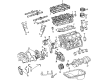
2003 Toyota Tundra Timing Belt
Part Number: 13568-YZZ03$58.42 MSRP: $81.32You Save: $22.90 (29%)Ships in 1-3 Business DaysProduct Specifications- Other Name: Belt Set, Timing; Engine Timing Belt; Timing Belt Kit
- Replaces: 13568-69095
- Item Weight: 1.00 Pounds
- Condition: New
- SKU: 13568-YZZ03
- Warranty: This genuine part is guaranteed by Toyota's factory warranty.


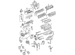
2003 Toyota Tundra Belt, Timing
Part Number: 13568-09070$61.13 MSRP: $85.81You Save: $24.68 (29%)Ships in 1-3 Business DaysProduct Specifications- Other Name: Engine Timing Belt; Timing Belt Kit; Timing Belt
- Manufacturer Note: (L)
- Replaces: 13568-59095
- Part Name Code: 13568
- Item Weight: 2.40 Pounds
- Item Dimensions: 13.4 x 11.6 x 2.2 inches
- Condition: New
- Fitment Type: Direct Replacement
- SKU: 13568-09070
- Warranty: This genuine part is guaranteed by Toyota's factory warranty.
2003 Toyota Tundra Timing Belt
Looking for affordable OEM 2003 Toyota Tundra Timing Belt? Explore our comprehensive catalogue of genuine 2003 Toyota Tundra Timing Belt. All our parts are covered by the manufacturer's warranty. Plus, our straightforward return policy and speedy delivery service ensure an unparalleled shopping experience. We look forward to your visit!
2003 Toyota Tundra Timing Belt Parts Q&A
- Q: How to service and repair the timing belt on 2003 Toyota Tundra?A: The timing belt repair and servicing process requires you to start by taking off the engine under cover while draining engine coolant and disconnecting the upper radiator hose. The PS pump disconnects from the engine after removing two PS air hoses from the air intake chamber and resonator followed by unbolting the PS pressure tube clamp to the frame and drive belt removal and finally unbolt and detach the PS pump. The procedure requires disconnecting the A/C compressor from the engine through the steps of removing the A/C compressor connector followed by the drive belt removal and unfastening the four bolts. The technician should disconnect the fan using fluid coupling and fan pulleys before removing the generator drive belt followed by removal of the No. 2 fan shroud together with fan pulleys and fluid coupling. Remove the A/C compressor bracket after breaking the five bolts then disconnect the upper radiator hose followed by disconnecting the camshaft position sensor connector and the four high-tension cord clamps before removing the six bolts from the No. 2 timing belt cover. Uninstall the fan bracket after removing the nut followed by the PS pump adjusting strut and detach the bolt and fan bracket along with the nut. Use the crankshaft pulley to position the No. 1 cylinder at TDC/compression while checking the perfect alignment of the first timing belt cover "0" timing mark and camshaft timing pulleys and No. 3 timing belt cover marks. The crankshaft pulley needs one full revolution adjustment when misalignment appears. To reuse the timing belt mark both the camshaft timing pulleys and the timing belt before placing them at the end of the No. 1 timing belt cover. Loosen the two bolts of the timing belt tensioner alternately before removing this component as well as the belt itself. Use Special Service Tool: 09960-10010 (09962-01000, 09963-01000) to sensibly loosen the pulley bolt on the RH camshaft timing pulley before removing the bolt, knock pin and camshaft timing pulley. The same tool functions for loosening the LH camshaft timing pulley bolt. To loosen the crankshaft pulley bolt utilize Special Service Tool: 09213-54015 (90119-08216), 09330-00021 followed by the removal of Special Service Tool: 09950-50013 (09551-05010, 09552-05010, 09553-05020, 09554-05031), pulley bolt, and pulley. Usage of Special Service Tool: 09950-50013 (09551-05010, 09552-05010, 09553-05020, 09554-05031) allows removal of the pulley with its bolt when required. The service requires removal of the starter wire bracket and No. 1 timing belt cover through the disconnection of two starter wire bracket bolts together with the four timing belt cover bolts. After this you can proceed to remove the timing belt guide and the timing belt. Use a new installation mark on the timing belt which corresponds to the drilled mark found on the crankshaft timing pulley in case previous installation marks vanished. First slide the No. 2 idler pulley off by removing its bolt and pulley before you put a 10 mm hexagon wrench to the No. 1 idler pulley to extract the pivot bolt and idler pulley and plate washer. The crankshaft timing pulley must be removed either manually or using Special Service Tool: 09950-50013 (09951-05010, 09952-05010, 09953-05020, 09954-05011) and a service bolt. The timing belt needs inspecting for defects while being checked to avoid contact with liquid or steam or bending or twisting and receiving proper installation without timing cover gasket damage. Muscle the idler pulleys for oil leakage and inspect both idler pulleys for normal operation before checking the timing belt tensioner for potential oil leakage while verifying its push rod movement. Measure the push rod length from the housing end to verify its position within 10.0 to 10.8 mm (0.394 to 0.425 inches). Put the crankshaft timing pulley into the key groove before sliding it on while avoiding contact between the sensor part and the pulley. The installation of No. 1 idler pulley requires adhesive on the pivot bolt while using a 10 mm hexagon wrench to add the plate washer and idler pulley before checking that the pulley bracket moves without resistance. The No. 2 idler pulley requires installation with its corresponding bolt following the requirement of proper movement. The installation of the timing belt requires a cold engine where the technician must align engine symbols on the crankshaft timing pulley and oil pump body before cleaning all pulleys. Fitting the timing belt guide with cup-facing side outside in while installing the No. 1 timing belt cover along with starter wire bracket requires gasket inspection for damage signs which need replacement when present. Use Special Service Tool: 09213-54015 (90119-08216), 09330-00021 to torque the crankshaft pulley bolt after positioning its set key within the key groove. Use Special Service Tool: 09960-10010 (09962-01000, 09963-01000) to tighten the bolt of the LH camshaft timing pulley after aligning its knock pin hole with the knock pin groove. The crankshaft pulley and camshaft timing marks should be aligned to set the No. 1 cylinder at TDC/compression position. The time should start with fitting the timing belt at the LH camshaft timing pulley while making sure the installation mark is facing the timing mark. Next step is to install the timing belt at the RH camshaft timing pulley to align all marks together with the knock pin properly set. Tighten the timing belt tensioner through static pressure on the push rod while aligning its holes before mounting the tensioner using two bolts to eliminate the hexagon wrench. To check valve timing perform two crankshaft pulley rotations from TDC to TDC while verifying that all pulleys match the timing marks. Mount the fan bracket together with the No. 2 timing belt cover and A/C compressor bracket while inspecting that all gaskets stay intact. Start by mounting the fan using fluid coupling and fan pulleys before placing in the No. 2 fan shroud. The procedure for generator drive belt adjustment must be completed before properly tightening both fan pulleys and fluid coupling then proceeding with connecting the A/C compressor to its proper torque specifications. To complete the procedure connect the PS pump into position with the engine while also reconnecting the upper radiator hose and filling the system with coolant and starting the engine and checking for leaks before reattaching the engine under cover and performing a road test which includes a check for noises, shocks, slipping and shift points as well as smooth operation before a second coolant level check.
Related 2003 Toyota Tundra Parts
 2003 Toyota Tundra Oil Filter
 2003 Toyota Tundra Timing Chain Tensioner
 2003 Toyota Tundra Valve Cover Gasket
 2003 Toyota Tundra Crankshaft Gear
 2003 Toyota Tundra Crankshaft Pulley
 2003 Toyota Tundra Crankshaft Thrust Washer Set
 2003 Toyota Tundra Cylinder Head
 2003 Toyota Tundra Dipstick Tube
 2003 Toyota Tundra Engine Mount
 2003 Toyota Tundra Harmonic Balancer
 2003 Toyota Tundra Intake Valve
 2003 Toyota Tundra Rod Bearing