×
ToyotaParts- Hello
- Login or Register
- Quick Links
- Live Chat
- Track Order
- Parts Availability
- RMA
- Help Center
- Contact Us
- Shop for
- Toyota Parts
- Scion Parts
My Garage
My Account
Cart
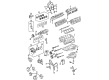
OEM 2004 Toyota Tundra Timing Belt
Engine Timing Belt- Select Vehicle by Model
- Select Vehicle by VIN
Select Vehicle by Model
orMake
Model
Year
Select Vehicle by VIN
For the most accurate results, select vehicle by your VIN (Vehicle Identification Number).
2 Timing Belts found


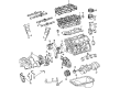
2004 Toyota Tundra Timing Belt
Part Number: 13568-YZZ03$58.42 MSRP: $81.32You Save: $22.90 (29%)Ships in 1-3 Business DaysProduct Specifications- Other Name: Belt Set, Timing; Engine Timing Belt; Timing Belt Kit
- Replaces: 13568-69095
- Item Weight: 1.00 Pounds
- Condition: New
- SKU: 13568-YZZ03
- Warranty: This genuine part is guaranteed by Toyota's factory warranty.


2004 Toyota Tundra Belt, Timing
Part Number: 13568-09070$61.13 MSRP: $85.81You Save: $24.68 (29%)Ships in 1-3 Business DaysProduct Specifications- Other Name: Engine Timing Belt; Timing Belt Kit; Timing Belt
- Manufacturer Note: (L)
- Replaces: 13568-59095
- Part Name Code: 13568
- Item Weight: 2.40 Pounds
- Item Dimensions: 13.4 x 11.6 x 2.2 inches
- Condition: New
- Fitment Type: Direct Replacement
- SKU: 13568-09070
- Warranty: This genuine part is guaranteed by Toyota's factory warranty.
2004 Toyota Tundra Timing Belt
Looking for affordable OEM 2004 Toyota Tundra Timing Belt? Explore our comprehensive catalogue of genuine 2004 Toyota Tundra Timing Belt. All our parts are covered by the manufacturer's warranty. Plus, our straightforward return policy and speedy delivery service ensure an unparalleled shopping experience. We look forward to your visit!
2004 Toyota Tundra Timing Belt Parts Q&A
- Q: How to service and repair the timing belt on 2004 Toyota Tundra?A: In order to service timing belt, drain the engine under cover, coolant, and unattach radiator hose. Disassemble PS pump and A/C compressor, loosen fan and cover the timing belt. Install all the parts and make sure they go in place by lining the crankshaft pulley, and checking the parts. Refill coolant, check it on leaks and road test.
Related 2004 Toyota Tundra Parts
 2004 Toyota Tundra Oil Filter
 2004 Toyota Tundra Timing Chain Tensioner
 2004 Toyota Tundra Valve Cover Gasket
 2004 Toyota Tundra Crankshaft Gear
 2004 Toyota Tundra Crankshaft Pulley
 2004 Toyota Tundra Crankshaft Thrust Washer Set
 2004 Toyota Tundra Cylinder Head
 2004 Toyota Tundra Dipstick Tube
 2004 Toyota Tundra Engine Mount
 2004 Toyota Tundra Harmonic Balancer
 2004 Toyota Tundra Intake Valve
 2004 Toyota Tundra Rod Bearing