×
ToyotaParts- Hello
- Login or Register
- Quick Links
- Live Chat
- Track Order
- Parts Availability
- RMA
- Help Center
- Contact Us
- Shop for
- Toyota Parts
- Scion Parts
My Garage
My Account
Cart
OEM 2003 Toyota Tundra Speed Sensor
Speed Control Sensor- Select Vehicle by Model
- Select Vehicle by VIN
Select Vehicle by Model
orMake
Model
Year
Select Vehicle by VIN
For the most accurate results, select vehicle by your VIN (Vehicle Identification Number).
6 Speed Sensors found


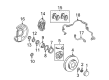
2003 Toyota Tundra ABS Sensor, Front Driver Side
Part Number: 89543-0C010$277.72 MSRP: $396.53You Save: $118.81 (30%)Ships in 1-3 Business DaysProduct Specifications- Other Name: Sensor, Speed, Front Left-Hand; ABS Wheel Speed Sensor, Front Left; Speed Sensor; Front Speed Sensor; Sensor, Speed, Front Driver Side; ABS Wheel Speed Sensor
- Position: Front Driver Side
- Part Name Code: 89543
- Item Weight: 1.30 Pounds
- Item Dimensions: 7.6 x 6.7 x 2.4 inches
- Condition: New
- Fitment Type: Direct Replacement
- SKU: 89543-0C010
- Warranty: This genuine part is guaranteed by Toyota's factory warranty.


2003 Toyota Tundra ABS Sensor, Front Passenger Side
Part Number: 89542-0C010$277.72 MSRP: $396.53You Save: $118.81 (30%)Ships in 1-3 Business DaysProduct Specifications- Other Name: Sensor, Speed, Front Right-Hand; ABS Wheel Speed Sensor, Front Right; Speed Sensor; Front Speed Sensor; Sensor, Speed, Front Passenger Side; ABS Wheel Speed Sensor
- Position: Front Passenger Side
- Part Name Code: 89542
- Item Weight: 1.30 Pounds
- Item Dimensions: 9.9 x 6.5 x 2.2 inches
- Condition: New
- Fitment Type: Direct Replacement
- SKU: 89542-0C010
- Warranty: This genuine part is guaranteed by Toyota's factory warranty.


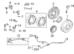
2003 Toyota Tundra ABS Sensor, Rear Passenger Side
Part Number: 89545-35020$249.88 MSRP: $356.78You Save: $106.90 (30%)Ships in 1-2 Business DaysProduct Specifications- Other Name: Sensor, Speed, Rear Right-Hand; ABS Wheel Speed Sensor, Rear Right; Speed Sensor; Rear Speed Sensor; Sensor, Speed, Rear Passenger Side; ABS Wheel Speed Sensor
- Position: Rear Passenger Side
- Part Name Code: 89545
- Item Weight: 0.70 Pounds
- Item Dimensions: 10.3 x 6.6 x 2.1 inches
- Condition: New
- Fitment Type: Direct Replacement
- SKU: 89545-35020
- Warranty: This genuine part is guaranteed by Toyota's factory warranty.

2003 Toyota Tundra ABS Sensor, Rear Driver Side
Part Number: 89546-35020$252.33 MSRP: $360.27You Save: $107.94 (30%)Ships in 1-2 Business DaysProduct Specifications- Other Name: Sensor, Speed, Rear Left-Hand; ABS Wheel Speed Sensor, Rear Left; Speed Sensor; Rear Speed Sensor; Sensor, Speed, Rear Driver Side; ABS Wheel Speed Sensor
- Position: Rear Driver Side
- Part Name Code: 89546
- Item Weight: 0.50 Pounds
- Item Dimensions: 9.9 x 6.5 x 2.1 inches
- Condition: New
- Fitment Type: Direct Replacement
- SKU: 89546-35020
- Warranty: This genuine part is guaranteed by Toyota's factory warranty.
- Product Specifications
- Other Name: Sensor, Speed, Front Left-Hand; ABS Wheel Speed Sensor, Front Left; ABS Sensor; Front Speed Sensor; Sensor, Speed, Front Driver Side
- Position: Front Driver Side
- Part Name Code: 89543
- Item Weight: 0.90 Pounds
- Item Dimensions: 10.3 x 6.6 x 2.2 inches
- Condition: New
- Fitment Type: Direct Replacement
- SKU: 89543-34020
- Warranty: This genuine part is guaranteed by Toyota's factory warranty.
- Product Specifications
- Other Name: Sensor, Speed, Front Right-Hand; ABS Wheel Speed Sensor, Front Right; ABS Sensor; Front Speed Sensor; Sensor, Speed, Front Passenger Side
- Position: Front Passenger Side
- Part Name Code: 89542
- Item Weight: 0.90 Pounds
- Item Dimensions: 10.3 x 6.7 x 2.1 inches
- Condition: New
- Fitment Type: Direct Replacement
- SKU: 89542-34020
- Warranty: This genuine part is guaranteed by Toyota's factory warranty.
2003 Toyota Tundra Speed Sensor
Looking for affordable OEM 2003 Toyota Tundra Speed Sensor? Explore our comprehensive catalogue of genuine 2003 Toyota Tundra Speed Sensor. All our parts are covered by the manufacturer's warranty. Plus, our straightforward return policy and speedy delivery service ensure an unparalleled shopping experience. We look forward to your visit!
2003 Toyota Tundra Speed Sensor Parts Q&A
- Q: How to service and repair the Transmission Speed Sensor on 2003 Toyota Tundra?A: Service and repair of the transmission speed sensor starts with propeller shaft removal before proceeding to remove the No. 1 vehicle speed sensor and speedometer driven gear and the No. 2 vehicle speed sensor. The transmission needs to be slightly elevated through a transmission jack while it rests on a stable support that lets you remove it from the crossmember. The service starts with removing 4 bolts from the rear mounting side of the engine rear mounting insulator before taking out the 4 nuts, bolts, washers, and crossmember. Start by removing the 4 bolts and engine rear mounting insulator from the extension housing and continuing with the removal of the 6 bolts and gasket and extension housing while using a plastic hammer or wooden block to help the extension housing come loose if required. To work on the 5VZ-FE you need to utilize a snap ring expander to take out the snap ring followed by removing the speedometer drive gear along with the ball. The procedure for the 2UZ-FE entails a snap ring expander for snap ring removal after which you should remove the speedometer drive gear. To remove and install the snap ring of the sensor rotor first apply a snap ring expander tool then use the key with the sensor rotor. The installation requires first using a snap ring expander to place the snap ring followed by insertion of the key along with sensor rotor. Use a snap ring expander to install the snap ring when working on the 5VZ-FE engine with a speedometer drive gear and ball in place. The speedometer drive gear requires installation before placing the snap ring with a snap ring expander tool on the 2UZ-FE sensor. The extension housing must receive threads of part no. 08833-00080 Three Bond 1344 Loctite 242 sealant or equivalent before the installation of a new gasket with its installation on the case using 6 bolts that reach 36 Nm (370 kgf-cm, 27 ft. lbs.) torque while noting that the two lower bolts are shorter. Add the 4 bolts onto the engine rear mounting insulator and torque them to 65 Nm and then add the crossmember with its 4 washers, bolts, and nuts torqued at 72 Nm, followed by torquing the 4 bolts on the rear mounting side to the engine rear mounting insulator to 18 Nm. The last step includes fitting the No. 2 vehicle speed sensor and speedometer driven gear followed by installing the No. 1 vehicle speed sensor and propeller shaft. Then, fill ATF while verifying the fluid level.
Related 2003 Toyota Tundra Parts
 2003 Toyota Tundra Wheel Bearing
 2003 Toyota Tundra Brake Caliper
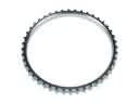 2003 Toyota Tundra ABS Reluctor Ring
 2003 Toyota Tundra Brake Caliper Piston
 2003 Toyota Tundra Brake Disc
 2003 Toyota Tundra Brake Line
 2003 Toyota Tundra Brake Shoe Set
 2003 Toyota Tundra Hydraulic Hose
 2003 Toyota Tundra Parking Brake Shoe
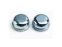 2003 Toyota Tundra Wheel Bearing Dust Cap
 2003 Toyota Tundra Wheel Cylinder
 2003 Toyota Tundra Wheel Cylinder Repair Kit