×
ToyotaParts- Hello
- Login or Register
- Quick Links
- Live Chat
- Track Order
- Parts Availability
- RMA
- Help Center
- Contact Us
- Shop for
- Toyota Parts
- Scion Parts
My Garage
My Account
Cart
OEM 2003 Toyota Camry Coil Springs
Strut Spring- Select Vehicle by Model
- Select Vehicle by VIN
Select Vehicle by Model
orMake
Model
Year
Select Vehicle by VIN
For the most accurate results, select vehicle by your VIN (Vehicle Identification Number).
19 Coil Springs found

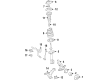
2003 Toyota Camry Coil Spring, Front
Part Number: 48131-06730$111.07 MSRP: $155.90You Save: $44.83 (29%)Ships in 1-3 Business DaysProduct Specifications- Other Name: Spring, Coil, Front; Coil Spring, Front; Coil Springs; Spring; Spring, Front Coil, Passenger Side; Spring, Front Coil, Driver Side
- Manufacturer Note: L=379.0
- Position: Front
- Item Weight: 7.10 Pounds
- Item Dimensions: 15.6 x 6.9 x 5.8 inches
- Condition: New
- Fitment Type: Direct Replacement
- SKU: 48131-06730
- Warranty: This genuine part is guaranteed by Toyota's factory warranty.

2003 Toyota Camry Coil Spring, Front
Part Number: 48131-AA160$107.89 MSRP: $151.45You Save: $43.56 (29%)Ships in 1-3 Business DaysProduct Specifications- Other Name: Spring, Coil, Front; Coil Spring, Front; Coil Springs; Spring, Front Coil, Passenger Side; Spring, Front Coil, Driver Side
- Manufacturer Note: L=359.5
- Position: Front
- Replaces: 48131-3T260
- Item Weight: 7.10 Pounds
- Item Dimensions: 16.4 x 7.1 x 6.1 inches
- Condition: New
- Fitment Type: Direct Replacement
- SKU: 48131-AA160
- Warranty: This genuine part is guaranteed by Toyota's factory warranty.
2003 Toyota Camry Coil Spring, Front
Part Number: 48131-06560$103.38 MSRP: $145.11You Save: $41.73 (29%)Ships in 1-3 Business DaysProduct Specifications- Other Name: Spring, Coil, Front; Coil Spring, Front; Coil Springs; Spring; Spring, Front Coil, Passenger Side; Spring, Front Coil, Driver Side
- Manufacturer Note: L=367.0
- Position: Front
- Item Weight: 6.80 Pounds
- Item Dimensions: 15.5 x 7.1 x 5.8 inches
- Condition: New
- Fitment Type: Direct Replacement
- SKU: 48131-06560
- Warranty: This genuine part is guaranteed by Toyota's factory warranty.
2003 Toyota Camry Coil Spring, Front
Part Number: 48131-AA180$98.85 MSRP: $138.76You Save: $39.91 (29%)Ships in 1-3 Business DaysProduct Specifications- Other Name: Spring, Coil, Front; Coil Spring, Front; Coil Springs; Spring; Spring, Front Coil, Passenger Side; Spring, Front Coil, Driver Side
- Manufacturer Note: L=395.5
- Position: Front
- Item Weight: 7.10 Pounds
- Item Dimensions: 15.8 x 6.9 x 5.9 inches
- Condition: New
- Fitment Type: Direct Replacement
- SKU: 48131-AA180
- Warranty: This genuine part is guaranteed by Toyota's factory warranty.
2003 Toyota Camry Coil Spring, Front
Part Number: 48131-AA170$95.65 MSRP: $134.27You Save: $38.62 (29%)Ships in 1-3 Business DaysProduct Specifications- Other Name: Spring, Coil, Front; Coil Spring, Front; Coil Springs; Spring; Spring, Front Coil, Passenger Side; Spring, Front Coil, Driver Side
- Manufacturer Note: L=391.0
- Position: Front
- Item Weight: 7.10 Pounds
- Item Dimensions: 15.8 x 6.9 x 5.8 inches
- Condition: New
- Fitment Type: Direct Replacement
- SKU: 48131-AA170
- Warranty: This genuine part is guaranteed by Toyota's factory warranty.

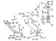
2003 Toyota Camry Coil Spring, Rear
Part Number: 48231-AA120$71.28 MSRP: $100.05You Save: $28.77 (29%)Ships in 1-3 Business DaysProduct Specifications- Other Name: Spring, Coil, Rear; Coil Spring, Rear; Coil Springs; Spring; Spring, Coil, Rear Passenger Side; Spring, Coil, Rear Driver Side
- Position: Rear
- Item Weight: 4.30 Pounds
- Item Dimensions: 17.0 x 11.0 x 5.7 inches
- Condition: New
- Fitment Type: Direct Replacement
- SKU: 48231-AA120
- Warranty: This genuine part is guaranteed by Toyota's factory warranty.
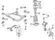
2003 Toyota Camry Coil Spring, Front
Part Number: 48131-AA150$106.89 MSRP: $150.04You Save: $43.15 (29%)Ships in 1-3 Business DaysProduct Specifications- Other Name: Spring, Coil, Front; Coil Spring, Front; Coil Springs; Spring; Spring, Front Coil, Passenger Side; Spring, Front Coil, Driver Side
- Manufacturer Note: L=373
- Position: Front
- Replaces: 48131-3T250
- Item Weight: 6.70 Pounds
- Item Dimensions: 16.6 x 7.0 x 5.9 inches
- Condition: New
- Fitment Type: Direct Replacement
- SKU: 48131-AA150
- Warranty: This genuine part is guaranteed by Toyota's factory warranty.
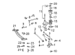
2003 Toyota Camry Coil Spring, Front
Part Number: 48131-AA120$110.55 MSRP: $155.17You Save: $44.62 (29%)Ships in 1-3 Business DaysProduct Specifications- Other Name: Spring, Coil, Front; Coil Spring, Front; Coil Springs; Spring, Front Coil, Passenger Side; Spring, Front Coil, Driver Side
- Manufacturer Note: L=366
- Position: Front
- Replaces: 48131-3T220
- Item Weight: 6.70 Pounds
- Item Dimensions: 16.1 x 7.4 x 5.9 inches
- Condition: New
- Fitment Type: Direct Replacement
- SKU: 48131-AA120
- Warranty: This genuine part is guaranteed by Toyota's factory warranty.
2003 Toyota Camry Coil Spring, Front
Part Number: 48131-AA140$101.59 MSRP: $142.61You Save: $41.02 (29%)Ships in 1-3 Business DaysProduct Specifications- Other Name: Spring, Coil, Front; Coil Spring, Front; Coil Springs; Spring; Spring, Front Coil, Passenger Side; Spring, Front Coil, Driver Side
- Manufacturer Note: L=352.5
- Position: Front
- Item Weight: 6.90 Pounds
- Item Dimensions: 16.1 x 7.0 x 5.9 inches
- Condition: New
- Fitment Type: Direct Replacement
- SKU: 48131-AA140
- Warranty: This genuine part is guaranteed by Toyota's factory warranty.

2003 Toyota Camry Coil Spring, Rear
Part Number: 48231-33480$91.15 MSRP: $127.95You Save: $36.80 (29%)Ships in 1-3 Business DaysProduct Specifications- Other Name: Spring, Coil, Rear; Coil Spring, Rear; Coil Springs; Spring; Spring, Coil, Rear Passenger Side; Spring, Coil, Rear Driver Side
- Position: Rear
- Item Weight: 5.70 Pounds
- Item Dimensions: 17.0 x 10.9 x 5.9 inches
- Condition: New
- Fitment Type: Direct Replacement
- SKU: 48231-33480
- Warranty: This genuine part is guaranteed by Toyota's factory warranty.
2003 Toyota Camry Coil Spring, Rear
Part Number: 48231-AA090$82.07 MSRP: $115.21You Save: $33.14 (29%)Ships in 1-3 Business DaysProduct Specifications- Other Name: Spring, Coil, Rear; Coil Spring, Rear; Coil Springs; Spring; Spring, Coil, Rear Passenger Side; Spring, Coil, Rear Driver Side
- Position: Rear
- Item Weight: 5.60 Pounds
- Item Dimensions: 16.7 x 10.8 x 5.7 inches
- Condition: New
- Fitment Type: Direct Replacement
- SKU: 48231-AA090
- Warranty: This genuine part is guaranteed by Toyota's factory warranty.
2003 Toyota Camry Coil Spring, Rear
Part Number: 48231-AA140$75.20 MSRP: $105.56You Save: $30.36 (29%)Ships in 1-3 Business DaysProduct Specifications- Other Name: Spring, Coil, Rear; Coil Spring, Rear; Coil Springs; Spring; Spring, Coil, Rear Passenger Side; Spring, Coil, Rear Driver Side
- Manufacturer Note: MEXICO SPEC
- Position: Rear
- Item Weight: 4.30 Pounds
- Item Dimensions: 17.0 x 11.0 x 5.6 inches
- Condition: New
- Fitment Type: Direct Replacement
- SKU: 48231-AA140
- Warranty: This genuine part is guaranteed by Toyota's factory warranty.
2003 Toyota Camry Coil Spring, Rear
Part Number: 48231-AA130$82.23 MSRP: $115.42You Save: $33.19 (29%)Product Specifications- Other Name: Spring, Coil, Rear; Coil Spring, Rear; Coil Springs; Spring; Spring, Coil, Rear Passenger Side; Spring, Coil, Rear Driver Side
- Position: Rear
- Item Weight: 4.10 Pounds
- Item Dimensions: 17.2 x 10.8 x 5.8 inches
- Condition: New
- Fitment Type: Direct Replacement
- SKU: 48231-AA130
- Warranty: This genuine part is guaranteed by Toyota's factory warranty.
- Product Specifications
- Other Name: Spring, Coil, Front; Coil Spring, Front; Coil Springs; Spring; Spring, Front Coil, Passenger Side; Spring, Front Coil, Driver Side
- Manufacturer Note: L=387.5
- Position: Front
- Item Weight: 7.10 Pounds
- Item Dimensions: 15.9 x 6.9 x 5.8 inches
- Condition: New
- Fitment Type: Direct Replacement
- SKU: 48131-AA200
- Warranty: This genuine part is guaranteed by Toyota's factory warranty.
- Product Specifications
- Other Name: Spring, Coil, Rear; Coil Spring, Rear; Coil Springs; Spring; Spring, Coil, Rear Passenger Side; Spring, Coil, Rear Driver Side
- Position: Rear
- Item Weight: 4.00 Pounds
- Item Dimensions: 17.2 x 10.6 x 5.7 inches
- Condition: New
- Fitment Type: Direct Replacement
- SKU: 48231-06270
- Warranty: This genuine part is guaranteed by Toyota's factory warranty.
- Product Specifications
- Other Name: Spring, Coil, Rear; Coil Spring, Rear; Coil Springs; Spring; Spring, Coil, Rear Passenger Side; Spring, Coil, Rear Driver Side
- Position: Rear
- Item Weight: 4.40 Pounds
- Item Dimensions: 18.0 x 11.1 x 6.1 inches
- Condition: New
- Fitment Type: Direct Replacement
- SKU: 48231-33490
- Warranty: This genuine part is guaranteed by Toyota's factory warranty.
- Product Specifications
- Other Name: Spring, Coil, Front; Coil Spring, Front; Coil Springs; Spring, Front Coil, Passenger Side; Spring, Front Coil, Driver Side
- Position: Front
- Item Weight: 6.70 Pounds
- Item Dimensions: 16.7 x 7.0 x 6.1 inches
- Condition: New
- Fitment Type: Direct Replacement
- SKU: 48131-3T240
- Warranty: This genuine part is guaranteed by Toyota's factory warranty.
- Product Specifications
- Other Name: Spring, Coil, Front; Coil Spring, Front; Coil Springs; Spring, Front Coil, Passenger Side; Spring, Front Coil, Driver Side
- Position: Front
- Item Weight: 7.20 Pounds
- Item Dimensions: 16.7 x 7.3 x 6.3 inches
- Condition: New
- Fitment Type: Direct Replacement
- SKU: 48131-3T210
- Warranty: This genuine part is guaranteed by Toyota's factory warranty.
- Product Specifications
- Other Name: Spring, Coil, Front; Coil Spring, Front; Coil Springs; Spring; Spring, Front Coil, Passenger Side; Spring, Front Coil, Driver Side
- Position: Front
- Item Weight: 6.70 Pounds
- Item Dimensions: 16.4 x 7.1 x 6.0 inches
- Condition: New
- Fitment Type: Direct Replacement
- SKU: 48131-3T230
- Warranty: This genuine part is guaranteed by Toyota's factory warranty.
2003 Toyota Camry Coil Springs
Looking for affordable OEM 2003 Toyota Camry Coil Springs? Explore our comprehensive catalogue of genuine 2003 Toyota Camry Coil Springs. All our parts are covered by the manufacturer's warranty. Plus, our straightforward return policy and speedy delivery service ensure an unparalleled shopping experience. We look forward to your visit!
2003 Toyota Camry Coil Springs Parts Q&A
- Q: How to overhaul the shock absorber with coil springs on 2003 Toyota Camry?A: In order to redesign shock absorber featuring coil spring, pull off the front wheel and take out the stabilizer link. Unscrew the lock nut, and then get rid of the shock absorber unit. Check and change where necessary. Install parts, proper torque specification and lastly, front wheel alignment.
Related 2003 Toyota Camry Parts
 2003 Toyota Camry Control Arm
 2003 Toyota Camry Ball Joint
 2003 Toyota Camry Sway Bar Link
 2003 Toyota Camry Shock Absorber
 2003 Toyota Camry Axle Shaft
 2003 Toyota Camry Coil Spring Insulator
 2003 Toyota Camry Front Cross-Member
 2003 Toyota Camry Lateral Link
 2003 Toyota Camry Shock and Strut Boot
 2003 Toyota Camry Strut Housing
 2003 Toyota Camry Sway Bar Bracket
 2003 Toyota Camry Sway Bar Bushing