×
ToyotaParts- Hello
- Login or Register
- Quick Links
- Live Chat
- Track Order
- Parts Availability
- RMA
- Help Center
- Contact Us
- Shop for
- Toyota Parts
- Scion Parts
My Garage
My Account
Cart
Front Suspension Components
2002 Toyota Sequoia Control Arm, Steering Knuckle, Shock Absorber, Strut Housing
Currently shopping for
2002 Toyota Sequoia
Change VehicleVehicle Options
8 Cyl 4.7 L GASVehicle Options
8 Cyl 4.7 L GASCategories Close X
Currently selected
Suspension
Other Categories
A/C & Heating
Air & Fuel Delivery
Belts & Cooling
Body & Hardware
Brakes
Charging & Starting
Driveline & Axles
Electrical
Emission Control & Exhaust
Engine
Headlights & Lighting
Interior & Exterior Trim
Maintenance & Lubrication
Steering
Transmission
How to use OE catalog
3 diagrams found for the vehicle you selected.Select your vehicle options to narrow down results.
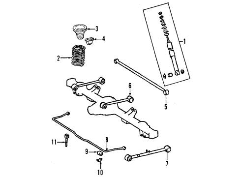
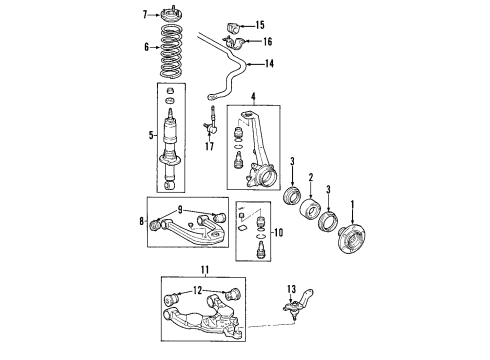
- 1.Front Suspension - Suspension Components
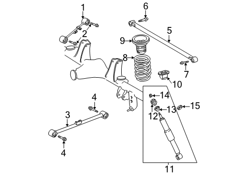
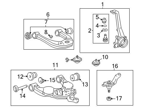
- 2.Front Suspension - Suspension Components (2WD)

- 3.Front Suspension - Suspension Components (4WD)
Sort by:
Ref No.
Ref No.
Part No. & Part Description
Price & Qty.
Part No. &
Part Description
Part Description
- 1

 MSRP: $345.96 Your Price: $242.311
 - 1


 MSRP: $320.34 Your Price: $224.371
- 1


 MSRP: $823.68 Your Price: $562.041
 - 1


 MSRP: $823.68 Your Price: $562.041
- 2


 MSRP: $160.83 Your Price: $114.581
- 2


 43310-39016
Upper Ball JointJoint Assembly, Front Upper Ball- Part Notes: 2WD;4WD
- Location: Driver Side;Passenger Side
MSRP: $71.18 Your Price: $51.131
- 3

 MSRP: $36.41 Your Price: $26.161
 - 3


 MSRP: $35.41 Your Price: $25.441
- 3
 90520-39180
Upper Ball Joint Snap RingRing, Shaft Snap- Part Notes: 2WD;4WD
- Location: Driver Side;Passenger Side
MSRP: $6.47 Your Price: $4.651
- 4
 MSRP: $823.68 Your Price: $562.041
 - 4MSRP: $823.68 Your Price: $562.041
- 4
 MSRP: $1.98 Your Price: $1.421
- 5

 MSRP: $221.21 Your Price: $156.261
 - 5


 MSRP: $215.06 Your Price: $151.921
 - 5
 MSRP: $202.91 Your Price: $143.341
- 5

 43324-39015
Upper Ball Joint CoverCover, Upper Ball Joint- Part Notes: 2WD;4WD
- Location: Driver Side;Passenger Side
MSRP: $17.61 Your Price: $12.661
- 6
 MSRP: $265.12 Your Price: $185.691
 - 6
- 6
 MSRP: $327.33 Your Price: $229.261
 - 6
 MSRP: $327.33 Your Price: $229.261
- 6

 MSRP: $350.95 Your Price: $245.801
 - 6
 MSRP: $321.84 Your Price: $225.421
- 7

 MSRP: $140.04 Your Price: $99.771
- 7


 48632-34010
Upper Control Arm BushingBush, Upper Arm- Part Notes: 2WD;4WD
- Location: Driver Side;Passenger Side
MSRP: $82.82 Your Price: $59.501
- 8
 MSRP: $350.95 Your Price: $245.801
 - 8MSRP: $321.84 Your Price: $225.421
- 8

 MSRP: $3.64 Your Price: $2.621
- 9MSRP: $82.82 Your Price: $59.501
- 9
 48304-34010
Spring BumperBumper Sub-Assembly, Front- Part Notes: 2WD, #1;4WD, #1
- Location: Driver Side;Passenger Side
MSRP: $55.87 Your Price: $40.141
- 10
 48305-34010
Spring BumperBumper Sub-Assembly, Front- Part Notes: 2WD, #2;4WD, #2
- Location: Driver Side;Passenger Side
MSRP: $49.89 Your Price: $35.841
- 10
 MSRP: $71.18 Your Price: $51.131
- 11

 48068-34020
Lower Control ArmArm Sub-Assembly, Suspension- Part Notes: 2WD;4WD;Sequoia; Right
- Location: Passenger Side
MSRP: $332.04 Your Price: $232.561 - 11
 48069-34020
Lower Control ArmArm Sub-Assembly, Suspension- Part Notes: 2WD;4WD;Sequoia; Left
- Location: Driver Side
MSRP: $328.43 Your Price: $230.03
- 12


 48654-34010
BushingsBush, Lower Arm- Part Notes: 2WD, #1;4WD, #1;Sequoia; Front
- Location: Driver Side;Passenger Side
MSRP: $141.37 Your Price: $100.711 - 12


 MSRP: $161.66 Your Price: $115.171
- 13
 MSRP: $161.66 Your Price: $115.171
- 13

 43340-39356
Lower Ball JointJoint Assembly, Lower Ball- Part Notes: Sequoia; Left;Tundra, Sequoia; Left
MSRP: $152.52 Your Price: $108.651 - 13


 43330-39466
Lower Ball JointJoint Assembly, Lower Ball- Part Notes: Sequoia; Right;Tundra, Sequoia; Right
MSRP: $152.52 Your Price: $108.651
- 14

 48409-34030
Bushing Adjust CamCam Sub-Assembly, Toe Adjust- Part Notes: 2WD, #2
- Location: Driver Side;Passenger Side
MSRP: $30.59 Your Price: $21.981 - 14

 48409-34020
Bushing Adjust CamCam Sub-Assembly, Toe Adjust- Part Notes: 2WD, #1;4WD, #1
- Location: Driver Side;Passenger Side
MSRP: $33.25 Your Price: $23.891
- 14
 MSRP: $232.85 Your Price: $164.491
 - 14
 MSRP: $190.61 Your Price: $134.641
- 15
 48409-34030
Bushing Adjust CamCam Sub-Assembly, Toe Adjust- Part Notes: 4WD, #2
- Location: Driver Side;Passenger Side
MSRP: $30.59 Your Price: $21.981
- 15


 MSRP: $35.25 Your Price: $25.321
- 15


 MSRP: $35.25 Your Price: $25.321
 - 15


 MSRP: $32.92 Your Price: $23.651
- 16

 MSRP: $55.37 Your Price: $39.781
 - 16
 MSRP: $55.37 Your Price: $39.781
- 16


 43340-39465
Lower Ball JointFront Lower Left Suspension Ball Joint Assembly- Part Notes: 2WD
- Location: Driver Side
MSRP: $180.13 Your Price: $127.241 - 16MSRP: $152.52 Your Price: $108.651
- 16MSRP: $152.52 Your Price: $108.651
- 17


 MSRP: $143.37 Your Price: $102.141
- 17

 90171-A0005
Lower Ball Joint Retainer NutNut, Castle- Part Notes: 2WD;4WD
- Location: Driver Side;Passenger Side
MSRP: $6.64 Your Price: $4.771

 43346-60011
Protector, Front Lower Ball Joint Dust Cover, RH- Location: Passenger Side
- Production Date: 02/2001-09/2003
- Fitting Vehicle Options: UCK35, 45
- Part Name Code: 43346A
MSRP: $40.07 Your Price: $28.79
 48069-34030
Arm Sub-Assy, Front Suspension, Lower NO.1 LH- Location: Lower Driver Side
- Production Date: 04/2002-09/2002
- Fitting Vehicle Options: UCK35, 45
- Part Name Code: 48069
- Replaced By: 48069-34020
MSRP: $328.43 Your Price: $230.03

 43340-39355
Joint Assy, Lower Ball, Front LH- Location: Front Driver Side
- Production Date: 09/2000-02/2001
- Fitting Vehicle Options: UCK35, 45
- Part Name Code: 43340A
- Replaced By: 43340-39356
MSRP: $152.52 Your Price: $108.65
")
") 90948-02177
90948-02177
Retainer, Cushion(For Front Suspension Upper Arm RH)- Location: Passenger Side
- Production Date: 09/2000-08/2004
- Fitting Vehicle Options: UCK35, 45
- Require Quantity: 2
- Package Quantity: 1
- Part Name Code: 48631A
- Replaced By: 90948-A2002
MSRP: $30.26 Your Price: $21.74
 48609-0C020
Support Sub-Assy, Front Suspension, RH- Location: Passenger Side
- Production Date: 09/2000-02/2002
- Fitting Vehicle Options: UCK35, 45.. 4HC
- Part Name Code: 48603
- Replaced By: 48609-0C021
MSRP: $140.04 Your Price: $99.77


 43330-39465
Joint Assy, Lower Ball, Front RH- Location: Front Passenger Side
- Production Date: 09/2000-02/2001
- Fitting Vehicle Options: UCK35, 45
- Part Name Code: 43330K
- Replaced By: 43330-39466
MSRP: $152.52 Your Price: $108.65
")
") 90179-10212
90179-10212
Nut(For Front Suspension Support)- Production Date: 09/2000-02/2002
- Fitting Vehicle Options: UCK35, 45.. 4HC
- Require Quantity: 6
- Package Quantity: 1
- Part Name Code: 48603A
- Replaced By: 90080-17206
MSRP: $3.48 Your Price: $2.50
")
") 90178-10015
90178-10015
Nut(For Front Suspension Support)- Production Date: 02/2002-08/2004
- Fitting Vehicle Options: UCK35, 45
- Require Quantity: 6
- Package Quantity: 1
- Part Name Code: 48603A
- Replaced By: 90080-17215
MSRP: $4.81 Your Price: $3.45
 48068-34030
Arm Sub-Assy, Front Suspension, Lower NO.1 RH- Location: Passenger Side
- Production Date: 04/2002-09/2002
- Fitting Vehicle Options: UCK35, 45
- Part Name Code: 48068
- Replaced By: 48068-34020
MSRP: $332.04 Your Price: $232.56

 48655-34020
Bush, Front Lower Arm, NO.2 RH- Location: Passenger Side
- Production Date: 04/2002-09/2002
- Fitting Vehicle Options: UCK35, 45
- Part Name Code: 48655D
- Replaced By: 48655-34010
MSRP: $161.66 Your Price: $115.17
OEM 2002 Toyota Sequoia Parts for Front Suspension Components
Genuine 2002 Toyota Sequoia parts are produced by Toyota with the official design and standards, thus they ensure a high quality throughout the production process. OEM parts are the ideal choice for people looking for new Front Suspension Components parts. With our competitive prices, we offer 2002 Toyota Sequoia Control Arm, Steering Knuckle, Shock Absorber, Strut Housing that fit tight budgets, while still including the manufacturer warranties, a hassle-free returns policy and quick shipping options.
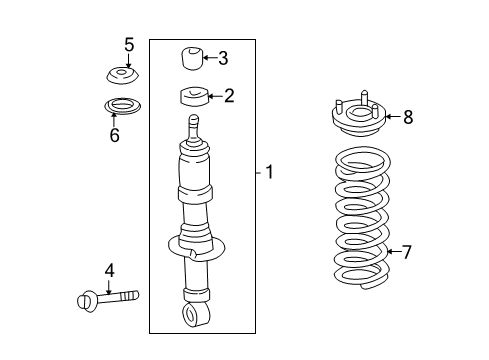
Control Arm, Shock Absorber Installation and Repair Tips for 2002 Toyota Sequoia
- Q: How to service and repair the front shock absorber with coil spring on 2002 Toyota Sequoia?A: In order to service and repair the front shock absorber with coil spring, remove the front wheel and detach the shock absorber of the lower suspension arm. Load the coil spring using a spring compressor after which the shock absorber has to be inspected. To replace, loosen and replace the bushing and reassemble and tighten everything back together and replace the front wheel.
- Q: How to service and repair the upper front control arm on 2002 Toyota Sequoia?A: To replace and repair the upper front control arm, relieve it of the shock absorber, disconnect the speed sensor wire harness clamps, and upper ball joint. Eliminate clips, brake lines, and fuel line. Change bushing and put on another one. Refit parts, torque correctness, and verify wheel position and sensor adjustment.