×
ToyotaParts- Hello
- Login or Register
- Quick Links
- Live Chat
- Track Order
- Parts Availability
- RMA
- Help Center
- Contact Us
- Shop for
- Toyota Parts
- Scion Parts
My Garage
My Account
Cart
OEM 2002 Toyota Highlander Starter Motor
Starter Ignition- Select Vehicle by Model
- Select Vehicle by VIN
Select Vehicle by Model
orMake
Model
Year
Select Vehicle by VIN
For the most accurate results, select vehicle by your VIN (Vehicle Identification Number).
1 Starter Motor found

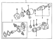
2002 Toyota Highlander Starter Assembly
Part Number: 28100-74260-84$158.04 MSRP: $222.38You Save: $64.34 (29%)Ships in 1-3 Business DaysProduct Specifications- Other Name: REMAN STARTER ASSY; Starter Motor; Starter
- Replaces: 28100-03100, 28100-74260
- Item Weight: 15.60 Pounds
- Item Dimensions: 13.8 x 6.5 x 6.3 inches
- Condition: New
- SKU: 28100-74260-84
- Warranty: This genuine part is guaranteed by Toyota's factory warranty.
2002 Toyota Highlander Starter Motor
Looking for affordable OEM 2002 Toyota Highlander Starter Motor? Explore our comprehensive catalogue of genuine 2002 Toyota Highlander Starter Motor. All our parts are covered by the manufacturer's warranty. Plus, our straightforward return policy and speedy delivery service ensure an unparalleled shopping experience. We look forward to your visit!
2002 Toyota Highlander Starter Motor Parts Q&A
- Q: How to service and repair the starter motor on 2002 Toyota Highlander?A: The first step to repair or service the starter motor begins with a starter yoke assembly removal procedure that requires starter cover removal followed by disconnecting the lead wire at C terminal and extracting the 2 through bolts to free the field frame with armature then disconnecting the O-ring from the field frame. The magnet starter switch assembly can be removed through two screws to release the starter housing and clutch assembly. The sequence continues with removal of the starter magnet switch return spring, starter idle gear pinion, starter idle gear retainer, and starter idle gear clutch roller until a magnetic finger can extract the steel ball from the clutch shaft hole. Two screws need to be unscrewed to remove the end cover together with the O-ring from the field frame when taking out the starter commutator end frame assembly. The brushing holder in the starter needs a screwdriver to pull back the spring before unconnecting the brushes from the holder then removing it. An ohmmeter measurement of the starter armature assembly segments for continuity should be performed before armature replacement when no continuity is found. The armature should be replaced when continuity exists between the commutator and armature coil core. Monitor the circle runout by using a dial gauge while ensuring it stays within 0.05 m m (0.0020 in.) limits and apply vernier calipers to verify the commutator diameter exceeds 29 mm (1.14 in.). Apply this test to the undercut depth because it should measure 0.2 mm (0.008 in.) minimum. Adjust if necessary. Test field coil connection between the lead wire and field coil brush lead while replacing the field frame when no continuity is present and check the field coil brush lead to field frame connection requiring field frame replacement when needed. The measurement of brush length will lead to replacements both for the brush holder and field frame if it falls below 8.5 mm (0.335 in.). Testing for electrical connection between starter brush holder positive and negative terminals should be performed along with needed repairs and replacements. A replacement magnetic switch becomes necessary when an inspection reveals no continuity between terminals 50 and C as well as between terminals 50 and the switch body. Assess the starter clutch sub-assembly for potential damage while checking that the pinion gear shows free counter-clockwise rotation with clockwise locking motion before deciding on replacement if needed. The proper procedure for removing the starter clutch sub-assembly includes bracing a brass bar in a vise, assembling the starter housing and clutch, lowering the pinion gear then hammering down the stop collar with a plastic-headed implement while using snap ring pliers to extract the snap ring to gain access to the stop collar, pinion gear, compression spring and starter housing components in order to disassemble the complete assembly. The installation sequence begins with combining the starter housing with starter clutch and compression spring after mounting these elements onto the brass bar. Push down the starter housing and install spring retainer and compression spring and pinion gear and stop collar before the addition of a new snap ring using snap ring pliers and subsequent shaft tapping to secure the assembly. Agree the starter armature assembly using grease on the bearings then insert it into the field frame. For the starter commutator end frame assembly apply an O-ring and install 2 screws while torquing them to 1.5 N.m (15 kgf.cm, 13 in.lbf). The starter yoke assembly installation process starts by adding grease to the steel ball inside the clutch shaft hole and continues with grease application on the starter magnet switch return spring and starter idle gear pinion and starter idle gear retainer and starter idle gear clutch roller along with the clutch gear and finishes by attaching the starter housing and clutch assembly with 2 screws which require a torque setting of 5.9 N.m (60 kgf.cm, 52 in.lbf). The assembly of the starter yoke requires installation of an O-ring to the field frame groove and alignment of the field frame protrusion with the magnetic switch groove followed by securing the field frame and armature assembly with 2 through bolts torqued to 5.9 N.m (60 kgf.cm, 52 in.lbf). The lead wire installation must be performed by connecting it to the C terminal using a nut also torqued to 5.9 N.m (60 kgf.cm, 52 in.lbf).
Related 2002 Toyota Highlander Parts
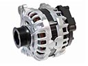 2002 Toyota Highlander Alternator
 2002 Toyota Highlander Battery Terminal
 2002 Toyota Highlander Alternator Bracket
 2002 Toyota Highlander Alternator Brush
 2002 Toyota Highlander Alternator Pulley
 2002 Toyota Highlander Armature
 2002 Toyota Highlander Battery Tray
 2002 Toyota Highlander Starter Brush
 2002 Toyota Highlander Starter Solenoid
 2002 Toyota Highlander Voltage Regulator