My Garage
Cart

OEM 2001 Toyota Highlander Starter Motor

Starter Ignition
  • Select Vehicle by Model
  • Select Vehicle by VIN
Select Vehicle by Model
Make
Model
Year
or
Select Vehicle by VIN
For the most accurate results, select vehicle by your VIN (Vehicle Identification Number).

1 Starter Motor found

  • 2001 Toyota Highlander Starter Motor - 28100-74260-84
    2001 Toyota Highlander Starter Motor Diagram - 28100-74260-84
    View related parts

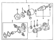
    2001 Toyota Highlander Starter Assembly

    Part Number: 28100-74260-84
    $158.04 MSRP: $222.38
    You Save: $64.34 (29%)
    Ships in 1-3 Business Days
    ADD TO CART
    Product Specifications
    • Other Name: REMAN STARTER ASSY; Starter Motor; Starter
    • Replaces: 28100-03100, 28100-74260
    • Item Weight: 15.60 Pounds
    • Item Dimensions: 13.8 x 6.5 x 6.3 inches
    • Condition: New
    • SKU: 28100-74260-84
    • Warranty: This genuine part is guaranteed by Toyota's factory warranty.
    More Info
    Fits the following 2001 Toyota Highlander Submodels:
    • Base, Limited | 4 Cyl 2.4 L GAS, 6 Cyl 3.0 L GAS

2001 Toyota Highlander Starter Motor

Looking for affordable OEM 2001 Toyota Highlander Starter Motor? Explore our comprehensive catalogue of genuine 2001 Toyota Highlander Starter Motor. All our parts are covered by the manufacturer's warranty. Plus, our straightforward return policy and speedy delivery service ensure an unparalleled shopping experience. We look forward to your visit!

2001 Toyota Highlander Starter Motor Parts Questions & Experts Answers

  • Q: How to service and repair the starter motor on 2001 Toyota Highlander?
    A: Service and repair operations for the starter motor start with starter yoke assembly removal followed by unhooking the lead wire from the C terminal and extracting the 2 through bolts to free the field frame with the armature unit from the unit then detaching the O-ring from the field frame. You need to start by removing the magnet starter switch assembly which requires 2 screw removal before extracting the starter housing along with clutch assembly when using a magnetic finger to pull out the steel ball from the clutch shaft hole. When working on the starter commutator end frame assembly open the field frame by removing its 2 screws and end cover and extract the O-ring. Holding the spring back with a screwdriver will allow disconnecting the brushes so you can remove the brush holder. You must use an ohmmeter to detect whether the starter armature has commutator segment continuity problems and if found replace the affected armature. An ohmmeter check for commutator-end-armature core circuit paths should be done to determine whether replacing the armature becomes necessary. A dial gauge should be used to measure circle runout until it reaches 0.05 mm (0.0020 in.) unless it needs correction through lathe operations. Check the commutator diameter using vernier calipers and determine whether it reaches at least 29 mm (1.14 in.), otherwise replace the armature. Undercut the commutator depth until it reaches 0.6 mm (0.024 in.) as minimum standard and no less than 0.2 mm (0.008 in.) but correct it with a hacksaw blade if depth falls below minimum. The inspection starts with an examination of field coil lead wire and field coil brush lead for electrical connections and a replacement of the field frame when no continuity is detected. Then check field coil brush lead and field frame junction for electrical connection while replacing the field frame if necessary. Rectify the brush holder and field frame when brush length measurement reveals values less than 8.5 mm (0.335 in.). A professional must check the positive (+) and negative (-) brush holder assembly for continuity then perform a brush holder replacement in case there is continuity observed. The magnet starter switch tests for continuous flow between terminals 50 and C and requires the magnetic switch be replaced when no continuity exists. The same test applies to terminals 50 and the switch body where replacement of the magnetic switch is needed. The starter clutch sub-assembly must be checked for gear tooth damage together with pinion gear counterclockwise rotation ability while maintaining clockwise movement. A new clutch assembly should be installed if these requirements are not met. The process to extract the starter clutch sub-assembly requires fitting a brass bar to a vise first and afterward inserting the starter housing along with clutch assembly followed by lowering the pinion gear and striking the stop collar with a plastic faced hammer before prying out the snap ring to finally remove the stop collar and pinion gear and compression spring and start disassembling the starter housing and starter clutch and clutch shaft along with compression spring. Begin installation by combining the starter housing with starter clutch, compression spring, then position these elements onto the brass bar before pushing down the starter housing to place the spring retainer and compression spring and pinion gear and stop collar. Finish by using snap ring pliers to install a new snap ring and tap the clutch shaft for securement. The starter armature assembly should be fitted to the field frame after applying grease to the bearings while installing an O-ring into the field frame groove and using 2 screws to secure the end frame at 1.5 N.m (15 kgf.cm, 13 in.lbf). Apply grease to the steel ball before installing it into the clutch shaft hole. Follow by greasing all necessary parts and installing the starter housing together with clutch assembly using 2 screws fastened at 5.9 N.m (60 kgf.cm, 52 in.lbf). To complete the assembly start with the O-ring positioned in the field frame groove followed by matching the field frame protrusion to the magnetic switch slot then fasten the assembly with two through-bolts at 5.9 N.m (60 kgf.cm, 52 in.lbf) torque. The last step involves wire connection from lead terminal C and nut torquing to 5.9 N.m (60 kgf.cm, 52 in.lbf).

Related 2001 Toyota Highlander Parts
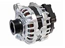