×
ToyotaParts- Hello
- Login or Register
- Quick Links
- Live Chat
- Track Order
- Parts Availability
- RMA
- Help Center
- Contact Us
- Shop for
- Toyota Parts
- Scion Parts
My Garage
My Account
Cart
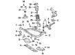
OEM 2001 Toyota Avalon Control Arm
Suspension Arm- Select Vehicle by Model
- Select Vehicle by VIN
Select Vehicle by Model
orMake
Model
Year
Select Vehicle by VIN
For the most accurate results, select vehicle by your VIN (Vehicle Identification Number).
2 Control Arms found

2001 Toyota Avalon Lower Control Arm, Driver Side
Part Number: 48069-07030$193.96 MSRP: $276.93You Save: $82.97 (30%)Ships in 1-3 Business DaysProduct Specifications- Other Name: Arm Sub-Assembly, Suspension; Suspension Control Arm, Front Left; Control Arm Assembly; Arm Sub-Assembly, Front Suspension, Lower Driver Side; Suspension Control Arm; Control Arm
- Position: Lower Driver Side
- Part Name Code: 48069
- Item Weight: 7.60 Pounds
- Item Dimensions: 19.7 x 3.3 x 15.2 inches
- Condition: New
- Fitment Type: Direct Replacement
- SKU: 48069-07030
- Warranty: This genuine part is guaranteed by Toyota's factory warranty.
2001 Toyota Avalon Lower Control Arm, Passenger Side
Part Number: 48068-07030$193.96 MSRP: $276.93You Save: $82.97 (30%)Ships in 1-3 Business DaysProduct Specifications- Other Name: Arm Sub-Assembly, Suspension; Suspension Control Arm; Control Arm Assembly; Control Arm; Arm Sub-Assembly, Front Suspension, Lower Passenger Side
- Position: Passenger Side
- Part Name Code: 48068
- Item Weight: 8.10 Pounds
- Item Dimensions: 19.3 x 3.2 x 15.2 inches
- Condition: New
- Fitment Type: Direct Replacement
- SKU: 48068-07030
- Warranty: This genuine part is guaranteed by Toyota's factory warranty.
2001 Toyota Avalon Control Arm
Looking for affordable OEM 2001 Toyota Avalon Control Arm? Explore our comprehensive catalogue of genuine 2001 Toyota Avalon Control Arm. All our parts are covered by the manufacturer's warranty. Plus, our straightforward return policy and speedy delivery service ensure an unparalleled shopping experience. We look forward to your visit!
2001 Toyota Avalon Control Arm Parts Q&A
- Q: How to service and repair the rear control arm on 2001 Toyota Avalon?A: Repair of the rear control arm starts with removing the rear wheel which should be torqued to 103 Nm (1,050 kgf-cm, 76 ft. lbs.). The parking brake cable needs detaching first before removing the bolt with 5.4 Nm torque (55 kgf-cm, 48 inch lbs.) to allow center exhaust pipe and strut rod removal. Then, two bolts and nuts must be removed at 113 Nm torque (1,150 kgf-cm, 83 ft. lbs.) while being careful not to rotate the nut. You should uninstall the No. 2 lower suspension arm by removing three nuts along with a suspension arm washer and washer with a torque value of 181 Nm (1,850 kgf-cm, 134 ft. lbs.) while keeping the paint mark oriented towards the rear when you reinstall the components. The steward should place a jack under the suspension member before taking off the 4 nuts along with the 2 bolts and 8 suspension member stoppers that need torques of 51 Nm (520 kgf-cm, 38 ft. lbs.) and 38 Nm (390 kgf-cm, 28 ft. lbs.). Lower the suspension member first and remove 2 bolts together with 2 washers and the No. 1 lower suspension arm while maintaining the paint mark at the back. The procedure for disassembly begins with loosening 2 lock nuts followed by turning the adjusting tube to break apart the No. 2 lower suspension arm before removing the 2 lock nuts. To assemble the No. 2 lower suspension arm use the adjusting tube while installing 2 lock nuts after verifying that A and B lengths are equal or less than 3.0 mm apart (0.118 inch). Adjust the arm length to 512.3 mm (20.169 inch). Adjustment of the rear wheel alignment must be done before torquing the 2 lock nuts to 56 Nm (570 kgf-cm, 41 ft. lbs.). Installation starts with the opposite order of removal steps until the rear wheel alignment must be checked.
Related 2001 Toyota Avalon Parts
 2001 Toyota Avalon Bump Stop
 2001 Toyota Avalon Coil Spring Insulator
 2001 Toyota Avalon Coil Springs
 2001 Toyota Avalon Control Arm Bushing
 2001 Toyota Avalon Front Cross-Member
 2001 Toyota Avalon Lateral Link
 2001 Toyota Avalon Shock And Strut Mount
 2001 Toyota Avalon Shock and Strut Boot
 2001 Toyota Avalon Strut Housing
 2001 Toyota Avalon Suspension Strut Rod
 2001 Toyota Avalon Sway Bar Bushing
 2001 Toyota Avalon Sway Bar Kit