×
ToyotaParts- Hello
- Login or Register
- Quick Links
- Live Chat
- Track Order
- Parts Availability
- RMA
- Help Center
- Contact Us
- Shop for
- Toyota Parts
- Scion Parts
My Garage
My Account
Cart
OEM 2000 Toyota Tacoma Rack And Pinion
Steering Rack And Pinion- Select Vehicle by Model
- Select Vehicle by VIN
Select Vehicle by Model
orMake
Model
Year
Select Vehicle by VIN
For the most accurate results, select vehicle by your VIN (Vehicle Identification Number).
6 Rack And Pinions found


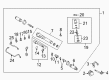
2000 Toyota Tacoma Steering Gear
Part Number: 44250-35042$547.17 MSRP: $801.89You Save: $254.72 (32%)Ships in 1-3 Business DaysProduct Specifications- Other Name: Gear Assembly, Power Steering; Rack and Pinion Assembly; Steering Gearbox; Gear Assembly; Gear Assembly, Power Steering(For Rack & Pinion)
- Replaces: 44250-35041, 44250-35040
- Part Name Code: 44250
- Item Weight: 28.30 Pounds
- Item Dimensions: 39.5 x 7.4 x 10.6 inches
- Condition: New
- Fitment Type: Direct Replacement
- SKU: 44250-35042
- Warranty: This genuine part is guaranteed by Toyota's factory warranty.

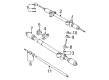
2000 Toyota Tacoma Rack
Part Number: 45521-35010$143.82 MSRP: $203.60You Save: $59.78 (30%)Ships in 1-3 Business DaysProduct Specifications- Other Name: Rack, Steering; Steering Gearbox; Steering Rack
- Part Name Code: 45521
- Item Weight: 5.60 Pounds
- Item Dimensions: 31.9 x 2.4 x 2.4 inches
- Condition: New
- Fitment Type: Direct Replacement
- SKU: 45521-35010
- Warranty: This genuine part is guaranteed by Toyota's factory warranty.

 Product Specifications
- Other Name: Rack Sub-Assembly, Power; Rack And Pinion Rack Gear, Front; Steering Gearbox; Steering Rack; Rack Sub-Assembly, Power Steering
- Position: Front
- Part Name Code: 44204
- Item Weight: 5.60 Pounds
- Item Dimensions: 32.4 x 3.2 x 2.7 inches
- Condition: New
- Fitment Type: Direct Replacement
- SKU: 44204-35020
- Warranty: This genuine part is guaranteed by Toyota's factory warranty.
 Product Specifications
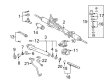
- Other Name: Gear Assembly, Steering; Rack and Pinion Assembly; Steering Gearbox; Gear Assembly
- Part Name Code: 45510
- Item Weight: 16.20 Pounds
- Item Dimensions: 50.2 x 10.5 x 6.8 inches
- Condition: New
- Fitment Type: Direct Replacement
- SKU: 45510-35010
- Warranty: This genuine part is guaranteed by Toyota's factory warranty.

 Product Specifications
- Other Name: Gear Assembly, Power Steering; Rack and Pinion Assembly; Steering Gearbox; Rack & Pinion; Gear Assembly; Gear Assembly, Power Steering(For Rack & Pinion)
- Part Name Code: 44250
- Item Weight: 21.30 Pounds
- Item Dimensions: 50.2 x 10.5 x 6.8 inches
- Condition: New
- Fitment Type: Direct Replacement
- SKU: 44250-04010
- Warranty: This genuine part is guaranteed by Toyota's factory warranty.
 Product Specifications
- Other Name: Rack Sub-Assembly, Power; Rack And Pinion Rack Gear, Front; Steering Gearbox; Steering Rack; Rack Sub-Assembly, Power Steering
- Position: Front
- Part Name Code: 44204
- Item Weight: 5.80 Pounds
- Item Dimensions: 33.6 x 3.1 x 2.7 inches
- Condition: New
- Fitment Type: Direct Replacement
- SKU: 44204-04010
- Warranty: This genuine part is guaranteed by Toyota's factory warranty.
2000 Toyota Tacoma Rack And Pinion
Looking for affordable OEM 2000 Toyota Tacoma Rack And Pinion? Explore our comprehensive catalogue of genuine 2000 Toyota Tacoma Rack And Pinion. All our parts are covered by the manufacturer's warranty. Plus, our straightforward return policy and speedy delivery service ensure an unparalleled shopping experience. We look forward to your visit!
2000 Toyota Tacoma Rack And Pinion Parts Q&A
- Q: How to disassemble and reassemble the Rack And Pinion on 2000 Toyota Tacoma?A: The manual rack and pinion needs to be placed in a vise with SST 09612-00012 and bolts 90105-10017 and 90170-10198 while avoiding excessive force on tightening the bolts. Mark both the tie rod end and rack end before you detach the RH and LH tie rod ends along with their locknuts. Cautiously pull the clamps off from RH and LH clips and rack boots at the same time by using a screwdriver to prevent boot damage then mark the components with a pen for identification. Pull off RH and LH rack ends and claw washers by driving the screwdriver into the washer while using a hammer to stake backward without striking the rack and pinion and using SST 09922-10010 to direct removal. Use markings to remove the bolt securing the rack housing No.2 bracket along with its grommet. SST 09631-10021 must be used to take off the rack guide spring cap and rack guide spring cap lock nut before proceeding to remove the rack guide spring, rack guide, and rack guide seat. First remove the dust cover along with the adjusting screw lock nut for the pinion bearing through the use of SST 09922-10010 before proceeding to remove the adjusting screw with the same SST. Pull the rack and pinion from its pinion housing side position by opening up the cutout area to obtain access to the pinion assembly. Pull out the rack and pinion without spinning it from the mounting position of the steering pinion housing. A dial indicator should be used to measure the runout and wear on the rack and pinion with maximum allowed runout set to 0.30 mm (0.0118 inch) while inspecting the back surface for any damage. The needle roller bearing needs inspection for damage while molybdenum disulfide lithium base grease should be applied inside the bearing and a new rack housing should be installed in case of failure. Replace the bushing by first loosening pressure screws then remove the damaged bushing for new installation with aligned positioning to the holes after coating the bushing with grease. The rotation and noise of the bearing should be checked before replacing the pinion assembly if it shows wear. The technician can replace the oil seal while using SST 09950-60010 (09951-00250), 09950-70010 (09951-07100) to remove the old seal and apply grease coating on a new seal lip before pressing it into position until it reaches the adjusting screw's surface. The reassembly process begins by coating all parts with molybdenum disulfide lithium base grease followed by rack and pinion installation from the steering pinion housing side where the notched section must face the pinion. Joint the pinion assembly to the rack and position its cutout correctly then verify the pinion end is tightly set inside the bearing while prohibiting tooth engagement. SST 09922-10010 should be used to install the pinion bearing adjusting screw with sealant applied to its threads while torquing it to 17 Nm (174 kgf-cm, 13 ft. lbs.) and applying additional sealant to the lock nut threads before torquing them to 88 Nm (894 kgf-cm, 65 ft. lbs.). Install the dust cover then place the rack guide seat and rack guide and rack guide spring followed by the rack guide spring cap which should have sealant on its threads before temporary installation. Measure total preload with SST after torquing the rack guide spring cap to 25 Nm but less than 1.3 Nm. Apply sealant on the rack guide spring cap threads before torquing it to 50 Nm (513 kgf-cm, 37 ft. lbs.) using SST and checking the preload again. Place the rack housing No.2 bracket and grommets onto the rack ends while carefully aligning matchmarks followed by tightening the bolt to 61 Nm (620 kgf-cm, 45 ft. lbs.). Screw the rack ends into place by first aligning their claws with rack and pinion grooves and then temporarily tightening the ends using SST to torque them to 61 Nm (621 kgf-cm, 45 ft. lbs.). Stake the washer with a brass bar and hammer which must avoid damaging the rack before installing RH and LH rack boots, clamps and clips with careful avoidance of boot damage or twisting and final tightening of new clamps. Finish the installation by screwing the lock nut and tie rod end into the rack end and then adjust the toe-in position before torquing the nut to 54 Nm (550 kgf-cm, 40 ft. lbs.).
Related 2000 Toyota Tacoma Parts
 2000 Toyota Tacoma Steering Wheel
 2000 Toyota Tacoma Power Steering Pump
 2000 Toyota Tacoma Steering Shaft
 2000 Toyota Tacoma Power Steering Hose
 2000 Toyota Tacoma Power Steering Reservoir
 2000 Toyota Tacoma Steering Column
 2000 Toyota Tacoma Power Steering Control Valve
 2000 Toyota Tacoma Rack and Pinion Boot
 2000 Toyota Tacoma Steering Column Cover
 2000 Toyota Tacoma Steering Gear Box
 2000 Toyota Tacoma Tie Rod End
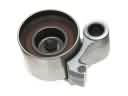 2000 Toyota Tacoma Timing Belt Idler Pulley