×
ToyotaParts- Hello
- Login or Register
- Quick Links
- Live Chat
- Track Order
- Parts Availability
- RMA
- Help Center
- Contact Us
- Shop for
- Toyota Parts
- Scion Parts
My Garage
My Account
Cart
OEM 2000 Toyota Camry Control Arm
Suspension Arm- Select Vehicle by Model
- Select Vehicle by VIN
Select Vehicle by Model
orMake
Model
Year
Select Vehicle by VIN
For the most accurate results, select vehicle by your VIN (Vehicle Identification Number).
5 Control Arms found


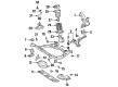
2000 Toyota Camry Arm Sub-Assembly, Suspension
Part Number: 48069-33031$245.23 MSRP: $350.13You Save: $104.90 (30%)Ships in 1-3 Business DaysProduct Specifications- Other Name: ARM SUB-ASSY, SUSPEN; Suspension Control Arm; Control Arm
- Position: Front Driver Side
- Replaces: 48069-06040, 48069-33030
- Item Weight: 1.40 Pounds
- Item Dimensions: 23.2 x 2.6 x 11.6 inches
- Condition: New
- SKU: 48069-33031
- Warranty: This genuine part is guaranteed by Toyota's factory warranty.

2000 Toyota Camry Lower Control Arm, Front Passenger Side
Part Number: 48068-33031$245.23 MSRP: $350.13You Save: $104.90 (30%)Ships in 1-3 Business DaysProduct Specifications- Other Name: Arm Sub-Assembly, Suspension; Front Right Control Arm; Track Control Arm
- Position: Front Passenger Side
- Replaces: 48068-06040, 48068-33030
- Item Weight: 1.40 Pounds
- Item Dimensions: 23.4 x 2.5 x 11.4 inches
- Condition: New
- SKU: 48068-33031
- Warranty: This genuine part is guaranteed by Toyota's factory warranty.

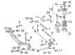
2000 Toyota Camry Control Arm, Rear
Part Number: 48710-33060$131.95 MSRP: $186.80You Save: $54.85 (30%)Ships in 1-3 Business DaysProduct Specifications- Other Name: Arm Assembly, Rear Suspension; Suspension Control Arm; Lateral Link; Lateral Arm; Front Lateral Arm
- Position: Rear
- Replaces: 48710-06010
- Item Weight: 5.10 Pounds
- Item Dimensions: 1.9 x 1.5 x 1.5 inches
- Condition: New
- SKU: 48710-33060
- Warranty: This genuine part is guaranteed by Toyota's factory warranty.

2000 Toyota Camry Lower Control Arm, Driver Side
Part Number: 48069-07030$193.96 MSRP: $276.93You Save: $82.97 (30%)Ships in 1-3 Business DaysProduct Specifications- Other Name: Arm Sub-Assembly, Suspension; Suspension Control Arm, Front Left; Control Arm Assembly; Arm Sub-Assembly, Front Suspension, Lower Driver Side; Suspension Control Arm; Control Arm
- Position: Lower Driver Side
- Part Name Code: 48069
- Item Weight: 7.60 Pounds
- Item Dimensions: 19.7 x 3.3 x 15.2 inches
- Condition: New
- Fitment Type: Direct Replacement
- SKU: 48069-07030
- Warranty: This genuine part is guaranteed by Toyota's factory warranty.
2000 Toyota Camry Lower Control Arm, Passenger Side
Part Number: 48068-07030$193.96 MSRP: $276.93You Save: $82.97 (30%)Ships in 1-3 Business DaysProduct Specifications- Other Name: Arm Sub-Assembly, Suspension; Suspension Control Arm; Control Arm Assembly; Control Arm; Arm Sub-Assembly, Front Suspension, Lower Passenger Side
- Position: Passenger Side
- Part Name Code: 48068
- Item Weight: 8.10 Pounds
- Item Dimensions: 19.3 x 3.2 x 15.2 inches
- Condition: New
- Fitment Type: Direct Replacement
- SKU: 48068-07030
- Warranty: This genuine part is guaranteed by Toyota's factory warranty.
2000 Toyota Camry Control Arm
Looking for affordable OEM 2000 Toyota Camry Control Arm? Explore our comprehensive catalogue of genuine 2000 Toyota Camry Control Arm. All our parts are covered by the manufacturer's warranty. Plus, our straightforward return policy and speedy delivery service ensure an unparalleled shopping experience. We look forward to your visit!
2000 Toyota Camry Control Arm Parts Q&A
- Q: How to service and repair the front control arm on 2000 Toyota Camry?A: Service and repair of the front control arm begins by detaching the front wheel which requires torque that reaches 103 Nm (1,050 kgf.cm, 76 ft. lbs.). You should disconnect the lower suspension arm from the lower ball joint by removing its two nuts and bolt while applying 127 Nm of torque equivalent to (1,300 kgf.cm, 94 ft. lbs.). First disconnect the lower suspension arm by removing the front side bolts using 206 Nm (2,100 kgf.cm, 152 ft. lbs.) torque then stripping out the rear side bolt and nut while maintaining the same torque value. Detach the lower suspension arm first and then remove its bushing stopper that is attached to the lower suspension arm shaft. The installation process should follow the removal sequence in reverse order while front wheel alignment must be checked after completion.
Related 2000 Toyota Camry Parts
 2000 Toyota Camry Ball Joint
 2000 Toyota Camry Control Arm Bushing
 2000 Toyota Camry Sway Bar Link
 2000 Toyota Camry Coil Springs
 2000 Toyota Camry Axle Shaft
 2000 Toyota Camry Bump Stop
 2000 Toyota Camry Front Cross-Member
 2000 Toyota Camry Lateral Link
 2000 Toyota Camry Shock And Strut Mount
 2000 Toyota Camry Shock and Strut Boot
 2000 Toyota Camry Steering Knuckle
 2000 Toyota Camry Strut Housing