×
ToyotaParts- Hello
- Login or Register
- Quick Links
- Live Chat
- Track Order
- Parts Availability
- RMA
- Help Center
- Contact Us
- Shop for
- Toyota Parts
- Scion Parts
My Garage
My Account
Cart
OEM Toyota Tacoma Timing Cover
Engine Timing Cover- Select Vehicle by Model
- Select Vehicle by VIN
Select Vehicle by Model
orMake
Model
Year
Select Vehicle by VIN
For the most accurate results, select vehicle by your VIN (Vehicle Identification Number).
11 Timing Covers found


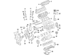
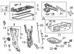
Toyota Tacoma Timing Cover Part Number: 11310-31014
$703.92 MSRP: $1031.60You Save: $327.68 (32%)Ships in 1-3 Business Days


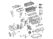
Toyota Tacoma Timing Cover, Lower Part Number: 11321-62900
$55.56 MSRP: $77.32You Save: $21.76 (29%)Ships in 1-3 Business Days

Toyota Tacoma Timing Cover, Upper Outer Part Number: 11322-62901
$113.27 MSRP: $159.00You Save: $45.73 (29%)Ships in 1-3 Business Days
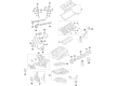
Toyota Tacoma Timing Cover Part Number: 11310-0P061
$597.11 MSRP: $875.07You Save: $277.96 (32%)Ships in 1-3 Business Days
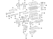
Toyota Tacoma Timing Cover Part Number: 11310-75073
$555.09 MSRP: $813.50You Save: $258.41 (32%)
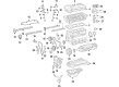
Toyota Tacoma Timing Cover Part Number: 11310-75090
$618.90 MSRP: $907.01You Save: $288.11 (32%)Ships in 1-3 Business Days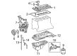
Toyota Tacoma Timing Cover Part Number: 11310-75074
$618.90 MSRP: $907.01You Save: $288.11 (32%)Ships in 1-3 Business Days
Toyota Tacoma Cover Assembly, Timing Chain Part Number: 11310-F0060
$247.08 MSRP: $352.78You Save: $105.70 (30%)Ships in 1-2 Business Days
Toyota Tacoma Cover Assembly, Timing Chain Or Belt Part Number: 11320-F0051
$271.31 MSRP: $387.37You Save: $116.06 (30%)Ships in 1-2 Business DaysToyota Tacoma Cover Assembly, Timing Chain Part Number: 11320-F0050
$271.32 MSRP: $387.38You Save: $116.06 (30%)Ships in 1-2 Business Days
Toyota Tacoma Timing Cover, Upper Inner Part Number: 11323-62050
Toyota Tacoma Timing Cover
Choose genuine Timing Cover that pass strict quality control tests. You can trust the top quality and lasting durability. Shopping for OEM Timing Cover for your Toyota Tacoma? Our website is your one-stop destination. We stock an extensive selection of genuine Toyota Tacoma parts. The price is affordable so you can save more. It only takes minutes to browse and find the exact fit. Easily add to cart and check out fast. Our hassle-free return policy will keep you stress-free. We process orders quickly for swift delivery. Your parts will arrive faster, so you can get back on the road sooner.
Toyota Tacoma Timing Cover Parts and Q&A
- Q: How to overhaul the timing cover sub-assembly on Toyota Tacoma?A:The first task in rebuilding the timing chain cover sub-assembly (2TR-FE) involves removal of the oil pump relief valve using a 27 mm socket wrench to discard the relief valve plug with its gasket and separate the valve spring and oil pump relief valve from its position. Start by removing the oil pump cover through the process of unfastening its 7 bolts. You should pull out the oil pump rotor set from the timing chain cover next. Check the oil pump relief valve operation by applying oil to it then dropping it into the relief valve hole; replacement of both the valve and timing chain cover might be needed if it does not drop smoothly. Install the rotors of the oil pump rotor set into the timing chain cover while turning the marks toward the exterior and verify easy rotation. A feeler gauge should check the rotor tip clearance and a replacement of the timing chain cover needs to occur when the measured value exceeds maximum allowed values. The maximum rotor body and side clearance thresholds can be determined using a feeler gauge and precision straight edge then the timing chain cover needs replacement if either threshold is exceeded. Place the oil pump gear set into the timing chain cover with its marks exposed to the outside while continuously rotating it. Apply engine oil to the gear set before installation. Insert the 7 bolts into the oil pump cover and torque them to 9.0 Nm (92 kgf-cm, 80 inch lbs.) before putting oil on the relief valve to place it with its spring into the timing chain cover hole. A new gasket should go on the relief valve plug before using a 27 mm socket wrench to tighten it to 49 Nm (500 kgf-cm, 36 ft. lbs.).
- Q: How to replace the Timing Cover on Toyota Tacoma?A:The installation process of a 2005 Toyota Truck Tacoma 2WD L4-2.7L (2TR-FE) Timing Chain Cover involves first removing the hood sub-assembly followed by fuel system pressure discharge and afterward removing the engine under cover sub-assembly No.1 and No.2 through four bolt removals apiece. Start the process by draining engine oil and coolant after removing the battery tray and battery. Follow the steps to detach the radiator support to frame seal LH and fan shroud and air cleaner cap sub-assembly together with air cleaner filter element sub-assembly and air cleaner case by unscrewing the existing 3 bolts. To begin the radiator hose No.2 removal and compressor detachment (when not equipped with air conditioning) before removing the radiator hose inlet. Remove the engine wire alongside the fuel hoses and air injection system No.1 hose before taking out the Exhaust Pipe assembly (tail and front) and manual or automatic transmission assembly and engine assembly. Perform the manual transmission service using Special Service Tool: 09213-54015 (91651-60855), 09330-00021 to take out the clutch cover assembly Clutch Disc assembly and flywheel sub-assembly. The service technician should remove the drive plate & ring gear assembly along with rear end plate through 2 bolt removal in addition to (generator assembly, V-ribbed belt tensioner assembly, idler pulley sub-assembly No.1, idle pulley assembly with bracket (air conditioning equipped) and Crankshaft Position Sensor, intake manifold to head gasket No.1 and cylinder head cover sub-assembly. The procedure for crankshaft pulley removal requires Special Service Tools: 09213-54015 (91651-60855), 09330-00021, 09950-50013 (09951-05010, 09952-05010, 09953-05010, 09954-05021). Along with these tools comes the use of oil level gauge sub-assembly, oil pan sub-assembly No.2 using Special Service Tool: 09032-00100, oil strainer sub-assembly, and oil pan sub-assembly. Separate the water by-pass pipe No.1 by taking off 2 nuts and 19 bolts and both nuts from the timing chain cover before carefully prying it off without causing damage. Fasten the 10 mm socket hexagon wrench to remove the 4 O-rings and the head straight screw plug. After removal of the water inlet along with Thermostat and timing gear case or timing chain case oil seal, install new oil seal assemblies. One should apply adhesive (Part No. 08833-00070, THREE BOND 1324 or equivalent) to the head straight screw plug before torquing it to 17 Nm (170 kgf-cm, 12 ft. lbs.). Install the timing chain cover after these steps. The timing chain cover requires installation of four new O-rings after applying continuous beads of seal packing (Part No. 08826-00080 or equivalent) where contact surface must be completely oil-free. After applying seal packing on the chain cover use within a three-minute time frame and bolt retention within a fifteen-minute timespan before allowing at least four hours of no engine start. The installation procedure involves aligning the slope on the oil pump drive rotor with the crankshaft followed by a loose attachment of 19 bolts and 2 nuts to the timing chain cover before final tightening according to specified order and torquing at 21 Nm (214 kgf-cm, 15 ft. lbs.) and 46 Nm (469 kgf-cm, 34 ft. lbs.). The installation requires a new gasket combined with pipe No.1 to have a torque specification of 18 Nm (178 kgf-cm, 13 ft. lbs.). The procedure requires reinstalling the oil pan sub-assembly followed by oil strainer sub-assembly then oil pan sub-assembly No.2 and finally oil level gauge sub-assembly. The correct installation sequence includes putting the crankshaft pulley into place using Special Service Tool: 09213-54015 (91651-60855), 09330-00021 followed by the cylinder head cover sub-assembly and intake manifold to head gasket No.1 and Camshaft Position Sensor together with crankshaft position sensor and idle pulley assembly with bracket and idler pulley sub-assembly No.1 and V-ribbed belt tensioner assembly and generator assembly and intake air connector and rear end plate with 2 bolts torqued at 18 Nm (178 kgf-cm, 13 ft. lbs.). For automatic transmission you must install the drive plate & ring gear sub-assembly followed by flywheel sub-assembly then clutch disc assembly and clutch cover assembly before reinstalling the engine assembly with automatic transmission assembly and manual transmission unit assembly. Add the exhaust pipe assembly front and tail section while connecting the engine wire with the air injection system No.1 hose and fuel vapor feed hose assembly and fuel hoses. The installation process includes water hose sub-assembly followed by the radiator hose inlet and compressor and magnetic clutch (if equipped for air conditioning) together with radiator hose No.2. Reinstall the vane pump assembly with correct torque of 12 Nm (122 kgf-cm, 9 ft. lbs.) together with the air cleaner case and air cleaner filter element sub-assembly followed by air cleaner cap sub-assembly fan shroud radiator support to frame seal LH and battery tray and battery. End the procedure by adding coolant and engine oil then checking the oil level before testing for fuel leaks and engine coolant and oil leaks and exhaust gas leaks. Then install both engine under covers with 30 Nm (306 kgf-cm, 22 ft. lbs.) torque and replace the hood sub-assembly.


Related Toyota Tacoma Parts
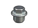 Toyota Tacoma Oil Drain Plug
 Toyota Tacoma Cylinder Head
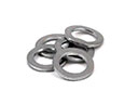 Toyota Tacoma Oil Drain Plug Gasket
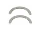 Toyota Tacoma Crankshaft Thrust Washer
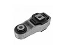 Toyota Tacoma Engine Mount Torque Strut
 Toyota Tacoma Intake Valve
 Toyota Tacoma Oil Pump Gasket
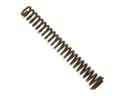 Toyota Tacoma Oil Pump Spring
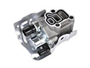 Toyota Tacoma Spool Valve
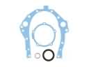 Toyota Tacoma Timing Cover Gasket
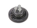 Toyota Tacoma Timing Idler Gear
 Toyota Tacoma Variable Timing Sprocket
Browse Toyota Tacoma Timing Cover by Years
2025 2024
2023
2022
2021
2020
2019
2018
2017
2016
2015
2014
2013
2012
2011
2010
2009
2008
2007
2006
2005
2004
2003
2002
2001
2000
1999
1998
1997
1996
1995