×
ToyotaParts- Hello
- Login or Register
- Quick Links
- Live Chat
- Track Order
- Parts Availability
- RMA
- Help Center
- Contact Us
- Shop for
- Toyota Parts
- Scion Parts
My Garage
My Account
Cart
OEM Toyota Prius Heater Core
HVAC Heater Core- Select Vehicle by Model
- Select Vehicle by VIN
Select Vehicle by Model
orMake
Model
Year
Select Vehicle by VIN
For the most accurate results, select vehicle by your VIN (Vehicle Identification Number).
4 Heater Cores found

Toyota Prius Unit Sub-Assembly, Heater Radiator Part Number: 87107-02230
$293.57 MSRP: $419.14You Save: $125.57 (30%)Ships in 1-3 Business Days
Toyota Prius Unit Sub-Assembly, Heater Radiator Part Number: 87107-47080
$344.12 MSRP: $504.31You Save: $160.19 (32%)Ships in 1-3 Business Days
Toyota Prius Heater Core Part Number: 87107-47060
$357.85 MSRP: $524.44You Save: $166.59 (32%)Ships in 1-3 Business Days
Toyota Prius Heater Core Part Number: 87107-47030
Toyota Prius Heater Core
Choose genuine Heater Core that pass strict quality control tests. You can trust the top quality and lasting durability. Shopping for OEM Heater Core for your Toyota Prius? Our website is your one-stop destination. We stock an extensive selection of genuine Toyota Prius parts. The price is affordable so you can save more. It only takes minutes to browse and find the exact fit. Easily add to cart and check out fast. Our hassle-free return policy will keep you stress-free. We process orders quickly for swift delivery. Your parts will arrive faster, so you can get back on the road sooner.
As known with other vehicles, the Heater Core in Toyota Prius vehicles plays the role of the additional heater that uses the heat from the car's engine to warm the interior of the car. Usually made from aluminum or brass, the core picks up hot coolant from the engine and heats the cabin air as the vehicle's fan passes through it. Higher level trims could be provided with mechanical units like electromechanical actuators and thermistors for the regulation of temperature, some of the models might include dual climate control features for driver and the passenger. Besides helping to warm the air, the heater core can also help in cooling the engine and dehumidifying the air in conditioned vehicles. However, problems like clogging, corrosion, or leakages are inevitable, which can be very expensive to solve since more often than not one has to half dismantle the dashboard to reach the heater core.
Toyota Prius Heater Core Parts and Q&A
- Q: How to service and repair the heater core on Toyota Prius?A:The refrigerant discharge process for refrigeration systems starts with Special Service Tool: 07110-58060 (07117-58080, 07117-58090, 07117-78050, 07117-88060, 07117-88070, 07117-88080). Detach the suction hose sub-assembly after verifying Special Service Tool: 09870-00015 installation and remove the 2 O-rings from the suction hose when sealing the opening with vinyl tape to stop moisture intrusion. After disconnecting cooler refrigerant pipe E with the same suction hose procedures, continue by removing heater water hoses A and B in preparation for coolant leaks. Separate the instrument panel sub-assembly containing the passenger Air Bag with its attached lower instrument panel and air duct rear No.3 by releasing all associated claws. The technician should extract the sunroof and then proceed with the removal of the heater control sections No.1, No.2, and No.3 and detach the defroster nozzle assembly together with the transmission control ECU assembly and both the ECM and network gateway ECU. Proceed to separate the instrument panel brace sub-assembly No.1 from other parts that include the air conditioning amplifier assembly and steering column assembly and instrument panel reinforcement assembly by disconnecting all required connectors and clamps. The service proceeds with removal of the air conditioner unit assembly, blower assembly, defroster lower nozzle assembly, air mix control servomotor, air outlet control servomotor, air conditioning tube & accessory assembly followed by the cooler expansion valve and heater radiator unit sub-assembly while accounting for potential coolant leaks. The procedure requires removal of cooler evaporator sub-assembly No.1 and evaporator temperature sensor once air duct No.1 and the quick heater assembly come out. The tech installs cooler evaporator sub-assembly No.1 with new O-rings that receive compressor oil (ND-OIL 11) application before proceeding to install the cooler expansion valve and air conditioning tube & accessory assembly. The tech completes the operation by adhering to torque specifications. The technician should reinstall the air conditioner unit assembly together with instrument panel reinforcement assembly as well as instrument panel brace sub-assembly No.1 while fully tightening the air conditioner unit assembly. The service technician should reinstall the steering column assembly then proceed with installation of lower instrument panel and instrument panel including passenger Air Bag assembly. Attach pipe E of the cooler refrigerant liquid and the suction hose sub-assembly while checking for refrigerant leaks. Use Special Service Tool: 07110-58060 (07117-58060, 07117-58070, 07117-58080, 07117-58090, 07117-78050, 07117-88060, 07117-88070, 07117-88080) to charge the refrigerant and add engine coolant until reaching 450 plus or minus 30 g (15.87 plus or minus 1.05 oz.). Verify coolant leakages after which warm up the compressor and do a comprehensive leak test and torque sensor zero-point calibration.

Related Toyota Prius Parts
 Toyota Prius A/C Accumulator
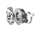 Toyota Prius A/C Compressor Clutch
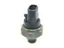 Toyota Prius A/C Compressor Cut-Out Switches
 Toyota Prius A/C Condenser
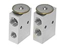 Toyota Prius A/C Expansion Valve
 Toyota Prius A/C Service Cap
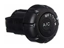 Toyota Prius A/C Switch
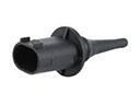 Toyota Prius Ambient Temperature Sensor
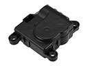 Toyota Prius Blend Door Actuator
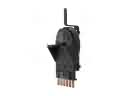 Toyota Prius Blower Control Switches
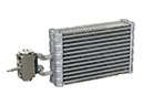 Toyota Prius Evaporator
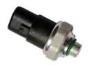 Toyota Prius HVAC Pressure Switch