×
ToyotaParts- Hello
- Login or Register
- Quick Links
- Live Chat
- Track Order
- Parts Availability
- RMA
- Help Center
- Contact Us
- Shop for
- Toyota Parts
- Scion Parts
My Garage
My Account
Cart
OEM Toyota Highlander Heater Core
HVAC Heater Core- Select Vehicle by Model
- Select Vehicle by VIN
Select Vehicle by Model
orMake
Model
Year
Select Vehicle by VIN
For the most accurate results, select vehicle by your VIN (Vehicle Identification Number).
8 Heater Cores found


Toyota Highlander Heater Core, Front Part Number: 87107-07030
$293.57 MSRP: $419.14You Save: $125.57 (30%)
Toyota Highlander Unit Sub-Assembly, Heater Radiator, Front Part Number: 87107-33120
$356.27 MSRP: $522.11You Save: $165.84 (32%)Ships in 1-2 Business Days
Toyota Highlander Heater Core, Rear Part Number: 87107-0E030
$356.27 MSRP: $522.11You Save: $165.84 (32%)Ships in 1-3 Business Days
Toyota Highlander Heater Core, Rear Part Number: 87107-0E060
$349.02 MSRP: $498.32You Save: $149.30 (30%)Ships in 1-3 Business Days
Toyota Highlander Heater Core, Front Part Number: 87107-06100
$349.02 MSRP: $498.32You Save: $149.30 (30%)Ships in 1-3 Business Days
Toyota Highlander Heater Core Part Number: 87107-48090

Toyota Highlander Heater Core Part Number: 87107-48040

Toyota Highlander Heater Core, Front Part Number: 87107-48080
Toyota Highlander Heater Core
Choose genuine Heater Core that pass strict quality control tests. You can trust the top quality and lasting durability. Shopping for OEM Heater Core for your Toyota Highlander? Our website is your one-stop destination. We stock an extensive selection of genuine Toyota Highlander parts. The price is affordable so you can save more. It only takes minutes to browse and find the exact fit. Easily add to cart and check out fast. Our hassle-free return policy will keep you stress-free. We process orders quickly for swift delivery. Your parts will arrive faster, so you can get back on the road sooner.
Toyota Highlander Heater Core Parts and Q&A
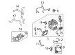
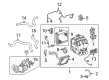
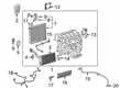
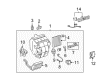
- Q: How to service and repair the heater core on Toyota Highlander?A:The heater core service requires HFC-134A draining through Special Service Tool: 07110-58060 (07117-58060, 07117-58070, 07117-58080, 07117-58090, 07117-78050, 07117-78060, 07117-88070, 07117-88080). The first piping clamp on cooler refrigerant suction pipe No.1 requires the insertion of Special Service Tool: 09870-00015 to unlock the clamp lock for smooth pipe clamp removal without damaging the tube structure. Use a suitable cap to cover open fittings while separate the cooler refrigerant suction hose No.1. The separation of cooler refrigerant liquid pipe A depends on Special Service Tool: 09870-00025 used in the same procedure. The heater inlet and outlet water hose clips should be gently pushed off to disconnect both hose lines. The instrument panel safety pad sub-assembly needs Special Service Tool: 09950-50012 (09951-05010, 09952-05010, 09953-05020, 09954-05020) for removal before using the same tool to disconnect the steering column assembly by removing 2 bolts and 2 nuts. The floor shift assembly needs 2 nuts and 4 transmission floor shift assembly nuts for removal to disconnect. To access Air Duct Rear No.2 technicians must begin by removing the side scuff plate then the floor carpet before removing the duct. Repeat for air duct rear No.1. First disconnect the connector clamp on instrument panel brace sub-assemblies No.1 and No.2 while removing their necessary bolts and nuts. Box out the ECM and multiplex network body ECU through the removal of their attached nuts. Disconnection of the instrument panel junction block assembly and skid control ECU assembly requires the removal of their bolts and nuts. The instrument panel reinforcement assembly can be removed after unbolting the 5 bolts and 4 nuts while the air conditioner unit assembly can be extracted by disconnecting connectors and unthreading 3 bolts and 2 nuts. Uninstall the air conditioning radiator assembly through duct detachment followed by screw and bracket removal. Detach air duct No.1 and the heater to register duct center through claw fitting release procedures. Screws need removal to take out the mode damper servo sub-assembly, wiring air conditioning harness sub-assembly and airmix damper servo sub-assembly. The heater radiator unit sub-assembly and both cooler thermistor No.1 and blower motor control components with blower resistor require screw removal. Usage of a 4 mm hexagon wrench enables the removal of bolts and O-rings on wiring air indicator harness sub-assembly No.2 while also removing the cooler expansion valve. You must disassemble the air conditioner radiator assembly before extracting cooler evaporator sub-assembly No.1 with its O-rings then reinstall it using 11 screws. Seal the cooler expansion valve on its mounting surface using new O-rings before tightening hexagon bolts using a 5.4 N.m torque value (55 kgf.cm, 48 in.lbf) with ND-OIL 8 or equivalent liquid. The air conditioner unit assembly should be reinstalled by tightening 3 bolts and 2 nuts to 9.8 N.m (100 kgf.cm, 87 in.lbf). Wiring should be restored after the installation process. After reinstallation of the instrument panel reinforcement assembly and the skid control ECU assembly together with the instrument panel junction block assembly and the ECM the technician must perform torque specifications according to all items. Install the instrument panel brace sub-assemblies and floor shift assembly while using correct bolts and nuts for assembly. Place the steering column assembly before the instrument panel safety pad sub-assembly. The technician must now install cooler refrigerant suction pipe No.1 along with liquid pipe A while lubricating fresh O-rings with compressor oil before charging the system with 650 g (22.93 oz.) +/- 50 g (1.76 oz.) of refrigerant. Engine heating up follows before checking for any refrigerant leakage.
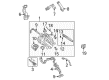
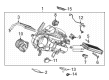
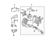
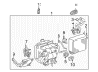
- Q: How to remove and install the heater core on Toyota Highlander?A:The procedure starts with removing the deck board NO.2 sub-assembly followed by the rear floor finish plate, back door weather strip, deck side trim box RH, rear door scuff plate RH and the rear door opening trim weather strip RH, deck side trim cover RH, deck trim side panel RH assembly. Then disconnect the heater water outlet hose by using pliers to slide the clip off. Hold the heater water pipes to avoid deformation as you place a drain pan or cloth for coolant leakage The procedure starts by gripping the heater water outlet hose clip with pliers to slide it off but maintain holding the heater water pipes to avoid deformation and place a drain pan or cloth below to catch coolant leaks. Follow the same approach to disconnect the heater water inlet hose. The next steps involve removing the foot air duct rear by disengaging its two clips followed by disconnecting air duct rear NO.5 while removing its wire harness clamp and two clips. The procedure to remove the rear heater assembly begins by detaching the washer hose clamp followed by removing four bolts and plate and disconnecting the heater relay NO.1 clamp and heater blower resistor connector before taking out the assembly using four bolts. The installation requires 4 bolts on the rear heater assembly to be tightened at 9.8 n.m (100 kgf.cm, 87 in.lbf) while following the specific numerical order for all bolts. Install the heater relay NO.1 and washer hose followed by connecting the heater blower resistor and placing the 4-bolt plate at the same torque. The installation steps involve putting in air duct rear NO.5 along with foot air duct rear and heater water inlet hose, heater water outlet hose followed by deck trim side panel assembly RH, deck side trim cover RH and deck side trim cover front LH followed by rear door opening trim weather strip RH accompanied by rear door scuff plate RH and deck side trim box RH and back door weather strip and rear floor finish plate and finally deck board sub-assembly.


Related Toyota Highlander Parts
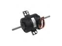 Toyota Highlander Blower Motor
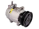 Toyota Highlander A/C Compressor
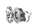 Toyota Highlander A/C Compressor Clutch
 Toyota Highlander A/C Condenser
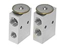 Toyota Highlander A/C Expansion Valve
 Toyota Highlander A/C Hose
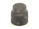 Toyota Highlander A/C Service Cap
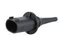 Toyota Highlander Ambient Temperature Sensor
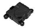 Toyota Highlander Blend Door Actuator
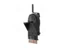 Toyota Highlander Blower Control Switches
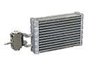 Toyota Highlander Evaporator
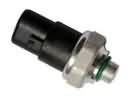 Toyota Highlander HVAC Pressure Switch