×
ToyotaParts- Hello
- Login or Register
- Quick Links
- Live Chat
- Track Order
- Parts Availability
- RMA
- Help Center
- Contact Us
- Shop for
- Toyota Parts
- Scion Parts
My Garage
My Account
Cart
OEM 2010 Scion xD Blower Motor
A/C Heater Blower Motor- Select Vehicle by Model
- Select Vehicle by VIN
Select Vehicle by Model
orMake
Model
Year
Select Vehicle by VIN
For the most accurate results, select vehicle by your VIN (Vehicle Identification Number).
1 Blower Motor found


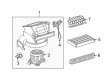
2010 Scion xD Blower Motor
Part Number: 87103-52141$137.35 MSRP: $194.43You Save: $57.08 (30%)Ships in 1-2 Business DaysProduct Specifications- Other Name: Motor Sub-Assembly, Blower; HVAC Blower Motor; Blower Assembly; Motor Sub-Assembly, Blower W/Fan
- Replaces: 87103-52140
- Part Name Code: 87103B
- Item Weight: 3.20 Pounds
- Item Dimensions: 12.5 x 12.4 x 8.2 inches
- Condition: New
- Fitment Type: Direct Replacement
- SKU: 87103-52141
- Warranty: This genuine part is guaranteed by Toyota's factory warranty.
2010 Scion xD Blower Motor
Looking for affordable OEM 2010 Scion xD Blower Motor? Explore our comprehensive catalogue of genuine 2010 Scion xD Blower Motor. All our parts are covered by the manufacturer's warranty. Plus, our straightforward return policy and speedy delivery service ensure an unparalleled shopping experience. We look forward to your visit!
2010 Scion xD Blower Motor Parts Q&A
- Q: How to install the Blower Motor and its associated components on 2010 Scion xD?A: Start installation by fastening the blower unit through its 3 screws. You must install the instrument panel reinforcement for manual and automatic transaxles after which comes the instrument panel wire installation and the main body ECU. Replace the drain cooler hose after you complete mounting the air duct assemblies including No. 3, No. 2 and No. 1 in the rear section and defroster nozzle assembly and No. 6 heater to register duct assembly. Mount the steering column assembly together with the brake pedal support and brake master cylinder push rod clevis. Mount the steering sliding yoke sub-assembly followed by installation of the column hole cover silencer sheet together with the instrument panel sub reinforcement. The power steering ECU assembly meets its connection points with the combination switch assembly before adding steering column upper and lower covers with steering wheel assembly and steering pad. The installation order includes attaching the antenna cord and hood lock control lever sub-assemblies to the lower instrument panel and afterward adding the No. 1 and No. 2 radio brackets, instrument panel box and under tray. The front console box receives installation following the process of cable connections between air mix assembly and air inlet assembly and defroster damper control cable assembly before the addition of the air conditioning panel assembly and the rear console box sub-assembly. The installer should put in place the console box carpet before adding the rear console box cover and upper console panel followed by the shift lever knob sub-assembly for manual transaxles. The production sequence requires the installation of cowl side trim boards together with No. 1 and No. 2 instrument panel under cover sub-assemblies and front door scuff plates. The installation sequence includes fitting upper instrument panel as well as glove compartment door assembly before proceeding with instrument cluster finish panel retainer and finish center panel sub-assembly. Proceed to install the combination meter assembly and instrument cluster finish panel before putting on the front pillar garnishes and front door opening trim Weather Strips. Begin by connecting both heater water hoses A to each other followed by installing the liquid tube assembly alongside the suction tube assembly. The sequence involves attaching the outer cowl top panel combined with the front air shutter seal RH and front wiper motor and link coupling to the cowl top ventilator louver LH and its sub-assembly. Place the hood to cowl top seal while setting front wiper arm and blade assemblies on both sides along with front wiper arm head caps. Phase in engine coolant while securing the negative battery cable with a torque setting of 5.4 Nm (55 kgf-cm, 48 in-lbf). After inspecting the SRS warning light the technician should charge refrigerant while checking for leaks during an engine warm-up period under which front wheels should remain aligned straight ahead.
Related 2010 Scion xD Parts
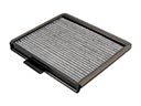 2010 Scion xD Cabin Air Filter
 2010 Scion xD A/C Accumulator
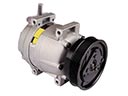 2010 Scion xD A/C Compressor
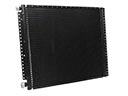 2010 Scion xD A/C Condenser
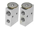 2010 Scion xD A/C Expansion Valve
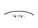 2010 Scion xD A/C Hose
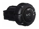 2010 Scion xD A/C Switch
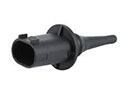 2010 Scion xD Ambient Temperature Sensor
 2010 Scion xD Blower Motor Resistor
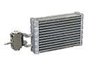 2010 Scion xD Evaporator
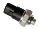 2010 Scion xD HVAC Pressure Switch
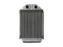 2010 Scion xD Heater Core