×
ToyotaParts- Hello
- Login or Register
- Quick Links
- Live Chat
- Track Order
- Parts Availability
- RMA
- Help Center
- Contact Us
- Shop for
- Toyota Parts
- Scion Parts
My Garage
My Account
Cart
OEM 2009 Toyota Venza Control Arm
Suspension Arm- Select Vehicle by Model
- Select Vehicle by VIN
Select Vehicle by Model
orMake
Model
Year
Select Vehicle by VIN
For the most accurate results, select vehicle by your VIN (Vehicle Identification Number).
2 Control Arms found


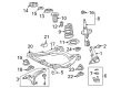
2009 Toyota Venza Arm Sub-Assembly, Front Suspension, Lower Driver Side
Part Number: 48069-0E050$159.79 MSRP: $226.20You Save: $66.41 (30%)Ships in 1-2 Business DaysProduct Specifications- Other Name: Arm Sub-Assembly, Suspension; Control Arm
- Position: Lower Driver Side
- Replaces: 48069-0T011, 48069-48070, 48069-48041, 48069-0T010, 48069-48040
- Part Name Code: 48069
- Item Weight: 8.50 Pounds
- Item Dimensions: 7.1 x 1.6 x 1.4 inches
- Condition: New
- Fitment Type: Direct Replacement
- SKU: 48069-0E050
- Warranty: This genuine part is guaranteed by Toyota's factory warranty.


2009 Toyota Venza Control Arm, Passenger Side
Part Number: 48068-0E050$159.79 MSRP: $226.20You Save: $66.41 (30%)Ships in 1-2 Business DaysProduct Specifications- Other Name: Arm Sub-Assembly, Suspension; Suspension Control Arm, Front Right; Control Arm Assembly; Lower Control Arm; Arm Sub-Assembly, Front Suspension, Lower Passenger Side
- Position: Passenger Side
- Replaces: 48068-48040, 48068-0T010, 48068-0T011, 48068-48041, 48068-48070
- Part Name Code: 48068
- Item Weight: 9.10 Pounds
- Item Dimensions: 7.1 x 1.4 x 1.5 inches
- Condition: New
- Fitment Type: Direct Replacement
- SKU: 48068-0E050
- Warranty: This genuine part is guaranteed by Toyota's factory warranty.
2009 Toyota Venza Control Arm
Looking for affordable OEM 2009 Toyota Venza Control Arm? Explore our comprehensive catalogue of genuine 2009 Toyota Venza Control Arm. All our parts are covered by the manufacturer's warranty. Plus, our straightforward return policy and speedy delivery service ensure an unparalleled shopping experience. We look forward to your visit!
2009 Toyota Venza Control Arm Parts Q&A
- Q: How to install the rear No. 1 Control Arm assembly LH on 2009 Toyota Venza?A: Attach the rear No. 1 suspension arm assembly LH to the rear suspension member using the bolt and nut but face its identification mark toward the rear of the vehicle. Safe bolt tightening is necessary because a stopper nut will be used. Set the assembly in the specified position with 7.6° standard angle and 1.96 in. (49.7 mm) length before torquing its bolt to 80 Nm (816 kgf-cm and 59 ft-lbf). Repetition of this method should then be performed for the rear No. 1 suspension arm assembly right-hand side. Rear suspension member installation requires a jack for position stabilization before installing both rear upper suspension member stoppers and rear lower suspension member stopper retainers using four nuts with two bolts according to manufacturing orientation specifications. Tighten each of the two nuts (A) to a torque level of 115 Nm (1173 kgf-cm, 85 ft-lbf) while using Special Service Tool: 09961-00950 along with a socket wrench (19 mm) for two approaches to reach the specified torque: 96 Nm (979 kgf-cm, 71 ft-lbf) when using the tool and 71 Nm (724 kgf-cm, 52 ft-lbf) when using it. The torque wrench requires a fulcrum length of 425 mm (1.39 ft.) maintaining its Install the bolt which connects the rear No. 1 suspension arm assembly LH to the rear axle carrier sub-assembly LH at 112 Nm (1142 kgf-cm, 83 ft-lbf) although the stopper nut requires temporary tightening of the bolt first. The repetitions must be completed on the rear No. 1 suspension arm assembly RH. The frame wire installation requires engagement of both clamps followed by the use of a connector for the No. 3 floor wire installation while keeping wire movements free from twisting motion. Fits the No. 1 floor under cover into place through installation of five clips. The rear No. 2 suspension arm assembly LH needs temporary tightening to the rear suspension member by using the rear suspension toe adjust cam sub-assembly, the No. 2 camber adjust cam and nut (B). Maintain the identification mark facing the rear of the vehicle while avoiding the rear suspension toe adjust cam sub-assembly from rotating during temporary tightening. You must tightly fasten the rear No. 2 suspension arm assembly LH to the rear axle carrier sub-assembly LH using bolt (A) and nut to 112 Nm (1142 kgf-cm, 83 ft-lbf) because the stopper nut enables this level of tightening. Apply the same procedure to the rear No. 2 suspension arm assembly RH. Fitting the rear height control sensor sub-assembly to the rear No. 2 suspension arm assembly RH requires use of the nut followed by tightening it to 5.4 Nm (55 kgf-cm, 48 in-lbf). Fitting the rear strut rod assembly LH and performing the steps for the RH side completes the installation. Place both parking brake cable assemblies No. 3 and No. 2 into their proper positions. You must first attach the propeller with center bearing shaft then apply full torque to the fastening. Perform an inspection of transfer oil while correctly adjusting its settings. Apply center exhaust pipe assembly placement according to the engine-specific installation instructions for exhaust pipes. Inspect for exhaust gas leakages during the step before installing the rear wheels and tightening them to 103 Nm (1050 kgf-cm, 76 ft-lbf). The suspension needs bouncing while the vehicle remains on the ground to achieve stable rear suspension operation. To tighten the rear No. 2 suspension arm assembly LH under standard vehicle height, the adjust cams must be aligned with the matchmarks on the rear suspension member sub-assembly before screwing the nut to 100 Nm (1020 kgf-cm, 74 ft-lbf) torque while ensuring the rear suspension toe adjust cam sub-assembly does not turn. Perform the same process on the rear No. 2 suspension arm assembly RH. The technician must perform wheel alignment checks on the rear wheels subsequent to initializing sensor signals. Following this the inspector should adjust the headlight aiming settings.
Related 2009 Toyota Venza Parts
 2009 Toyota Venza Shock Absorber
 2009 Toyota Venza Coil Spring Insulator
 2009 Toyota Venza Coil Springs
 2009 Toyota Venza Crossmember Bushing
 2009 Toyota Venza Lateral Link
 2009 Toyota Venza Rear Crossmember
 2009 Toyota Venza Shock And Strut Mount
 2009 Toyota Venza Shock and Strut Boot
 2009 Toyota Venza Strut Housing
 2009 Toyota Venza Sway Bar Bracket
 2009 Toyota Venza Sway Bar Bushing
 2009 Toyota Venza Sway Bar Link