×
ToyotaParts- Hello
- Login or Register
- Quick Links
- Live Chat
- Track Order
- Parts Availability
- RMA
- Help Center
- Contact Us
- Shop for
- Toyota Parts
- Scion Parts
My Garage
My Account
Cart
OEM 2009 Toyota Venza Rear Crossmember
Rear Suspension Crossmember- Select Vehicle by Model
- Select Vehicle by VIN
Select Vehicle by Model
orMake
Model
Year
Select Vehicle by VIN
For the most accurate results, select vehicle by your VIN (Vehicle Identification Number).
2 Rear Crossmembers found

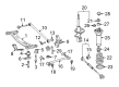
2009 Toyota Venza Suspension Crossmember, Rear
Part Number: 51206-06103$668.96 MSRP: $980.37You Save: $311.41 (32%)Ships in 1-3 Business DaysProduct Specifications- Other Name: Member Sub-Assembly, Rear; Suspension Subframe Crossmember, Rear; Crossmember; Member Sub-Assembly, Rear Suspension
- Position: Rear
- Replaces: 51206-06100, 51206-0E030, 51206-06102, 51206-06051, 51206-06101, 51206-06050
- Part Name Code: 51206A
- Item Weight: 19.10 Pounds
- Item Dimensions: 48.5 x 27.1 x 13.0 inches
- Condition: New
- Fitment Type: Direct Replacement
- SKU: 51206-06103
- Warranty: This genuine part is guaranteed by Toyota's factory warranty.

 Product Specifications
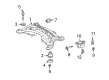
- Other Name: Member Sub-Assembly, Rear; Suspension Subframe Crossmember, Rear; Member Sub-Assembly, Rear Suspension
- Position: Rear
- Replaces: 51206-0T020
- Part Name Code: 51206A
- Condition: New
- Fitment Type: Direct Replacement
- SKU: 51206-0T021
- Warranty: This genuine part is guaranteed by Toyota's factory warranty.
2009 Toyota Venza Rear Crossmember
Looking for affordable OEM 2009 Toyota Venza Rear Crossmember? Explore our comprehensive catalogue of genuine 2009 Toyota Venza Rear Crossmember. All our parts are covered by the manufacturer's warranty. Plus, our straightforward return policy and speedy delivery service ensure an unparalleled shopping experience. We look forward to your visit!
2009 Toyota Venza Rear Crossmember Parts Q&A
- Q: How to remove the Rear Crossmember on 2009 Toyota Venza?A: The removal process of AWD rear suspension member starts by taking off rear wheels and the center exhaust pipe assembly. Begin by taking off the propeller assembly with center bearing shaft followed by dividing the left and right rear speed sensors after detaching their bolts. The next step is to remove nuts from the rear axle shafts before disconnecting the assemblies of No. 3 and No. 2 parking brake cables. The repair process starts by taking off No. 1 floor under cover and both rear strut rod assemblies and the rear height control sensor sub-assembly whenever HID headlights exist with the system. Hence remove both rear No. 2 suspension arm assemblies while moving on to separate the rear No. 1 suspension arm assemblies. The mechanic should drain differential oil followed by removing rear drive shaft assemblies with their attached snap rings from both sides. The procedure requires disconnecting the connectors then unclipping clamps on the frame wire and No. 3 floor wire. A jack equipped with three wooden blocks should support the rear suspension member while technicians remove four nuts, two bolts and two rear lower suspension member stopper retainers before lowering the member with caution to prevent damage. Start by discarding the rear No. 1 suspension arm assemblies followed by removing the rear differential carrier assembly with its differential support and finishing with the rear No. 1 and No. 2 differential mount cushions. To detach the rear suspension member body mounting front cushion on the LH side utilize Special Service Tool: 09830-10010 applying grease to the tool threads and tighten it gradually. Perform this sequence once again on the RH side. Special Service Tool: 09710-30050 allows removal of the rear mounting cushions after applying the same care as previous steps while the cushions should be removed when they reach 6 mm in projection. The procedure ends by taking out the hole plugs along with rear No. 2 body mounting bracket sub-assemblies from both sides and the stud bolts from each side.
Related 2009 Toyota Venza Parts
 2009 Toyota Venza Shock Absorber
 2009 Toyota Venza Coil Spring Insulator
 2009 Toyota Venza Coil Springs
 2009 Toyota Venza Control Arm
 2009 Toyota Venza Crossmember Bushing
 2009 Toyota Venza Lateral Link
 2009 Toyota Venza Shock And Strut Mount
 2009 Toyota Venza Steering Knuckle
 2009 Toyota Venza Sway Bar Bracket
 2009 Toyota Venza Sway Bar Bushing
 2009 Toyota Venza Sway Bar Kit
 2009 Toyota Venza Sway Bar Link