×
ToyotaParts- Hello
- Login or Register
- Quick Links
- Live Chat
- Track Order
- Parts Availability
- RMA
- Help Center
- Contact Us
- Shop for
- Toyota Parts
- Scion Parts
My Garage
My Account
Cart
OEM 2009 Toyota Sienna Axle Shaft
Car Axle Shaft- Select Vehicle by Model
- Select Vehicle by VIN
Select Vehicle by Model
orMake
Model
Year
Select Vehicle by VIN
For the most accurate results, select vehicle by your VIN (Vehicle Identification Number).
6 Axle Shafts found


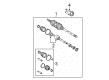
2009 Toyota Sienna Axle Assembly, Passenger Side
Part Number: 43410-08030$364.89 MSRP: $561.28You Save: $196.39 (35%)Product Specifications- Other Name: Shaft Assembly, Front Drive; CV Axle Assembly, Front Right; GSP Cv Axle; Axle Shaft; Shaft Assembly, Front Drive, Passenger Side; CV Axle Assembly
- Position: Passenger Side
- Part Name Code: 43410
- Item Weight: 30.00 Pounds
- Item Dimensions: 50.9 x 6.2 x 6.3 inches
- Condition: New
- Fitment Type: Direct Replacement
- SKU: 43410-08030
- Warranty: This genuine part is guaranteed by Toyota's factory warranty.

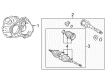
2009 Toyota Sienna Outer CV Joint, Driver Side
Part Number: 42370-09007$259.52 MSRP: $370.53You Save: $111.01 (30%)Ships in 1-3 Business DaysProduct Specifications- Other Name: Shaft Assembly, Rear Drive; CV Joint; Outer Joint Assembly; Shaft Assembly, Rear Drive Outboard Joint, Driver Side; Shaft Assembly, Rear Drive Outboard Joint
- Position: Driver Side
- Item Weight: 13.50 Pounds
- Item Dimensions: 32.5 x 6.0 x 5.1 inches
- Condition: New
- Fitment Type: Direct Replacement
- SKU: 42370-09007
- Warranty: This genuine part is guaranteed by Toyota's factory warranty.

2009 Toyota Sienna Axle Assembly, Driver Side
Part Number: 43420-08031$431.97 MSRP: $633.05You Save: $201.08 (32%)Ships in 1-3 Business DaysProduct Specifications- Other Name: Shaft Assembly, Front Drive; CV Axle Assembly, Front Left; GSP Cv Axle; Axle Shaft; Shaft Assembly, Front Drive, Driver Side; CV Axle Assembly
- Position: Driver Side
- Part Name Code: 43420
- Item Weight: 18.90 Pounds
- Item Dimensions: 31.3 x 5.2 x 5.2 inches
- Condition: New
- Fitment Type: Direct Replacement
- SKU: 43420-08031
- Warranty: This genuine part is guaranteed by Toyota's factory warranty.

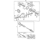
2009 Toyota Sienna Axle Shaft Assembly, Rear
Part Number: 42340-08010$396.78 MSRP: $581.49You Save: $184.71 (32%)Ships in 1-3 Business DaysProduct Specifications- Other Name: Shaft Assembly, Rear Drive; CV Axle Assembly, Rear, Rear Left, Rear Right; GSP Cv Axle; Axle Shaft; Axle Assembly; Shaft Assembly, Rear Drive, Passenger Side; Shaft Assembly, Rear Drive, Driver Side; CV Axle Assembly
- Position: Rear
- Item Weight: 16.10 Pounds
- Item Dimensions: 28.4 x 8.6 x 7.4 inches
- Condition: New
- Fitment Type: Direct Replacement
- SKU: 42340-08010
- Warranty: This genuine part is guaranteed by Toyota's factory warranty.
2009 Toyota Sienna Axle Assembly, Driver Side
Part Number: 43420-08020$298.66 MSRP: $452.96You Save: $154.30 (35%)Product Specifications- Other Name: Shaft Assembly, Front Drive; CV Axle Assembly, Front Left; GSP Cv Axle; Axle Shaft; Shaft Assembly, Front Drive, Driver Side; CV Axle Assembly
- Position: Driver Side
- Part Name Code: 43420
- Item Weight: 20.60 Pounds
- Item Dimensions: 30.1 x 5.3 x 5.2 inches
- Condition: New
- Fitment Type: Direct Replacement
- SKU: 43420-08020
- Warranty: This genuine part is guaranteed by Toyota's factory warranty.
- Product Specifications
- Other Name: Shaft Assembly, Front Drive; CV Axle Assembly, Front Right; GSP Cv Axle; Axle Shaft; Shaft Assembly, Front Drive, Passenger Side; CV Axle Assembly
- Position: Passenger Side
- Part Name Code: 43410
- Item Weight: 19.50 Pounds
- Item Dimensions: 47.8 x 5.5 x 5.5 inches
- Condition: New
- Fitment Type: Direct Replacement
- SKU: 43410-08041
- Warranty: This genuine part is guaranteed by Toyota's factory warranty.
2009 Toyota Sienna Axle Shaft
Looking for affordable OEM 2009 Toyota Sienna Axle Shaft? Explore our comprehensive catalogue of genuine 2009 Toyota Sienna Axle Shaft. All our parts are covered by the manufacturer's warranty. Plus, our straightforward return policy and speedy delivery service ensure an unparalleled shopping experience. We look forward to your visit!
2009 Toyota Sienna Axle Shaft Parts Q&A
- Q: How to Remove and Replace an Axle Shaft Assembly on 2009 Toyota Sienna?A: You can start the axle shaft assembly removal process by draining automatic transaxle fluid through drain plug removal followed by new gasket installation and drain plug torquing to 49 Nm (500 kgf-cm, 36 ft-lbf). The transfer oil of 4WD vehicles needs draining before maintenance. Apply Special Service Tool: 09930-00010 along with a hammer to unstake the LH nut of the front axle shaft. Use the hammer until the nut is fully loosened to avoid drive shaft screw damage. The procedure to remove the lock axle hub LH nut requires activation of vehicle braking. Begin the front stabilizer link assembly separation by taking out the nut from the LH side and apply a 6 mm hexagon wrench on the ball joint stud when it moves. Circularize the speed sensor front LH before extracting the bolt and you should detach the shock absorber while preserving its structural integrity then release the bolt to disconnect the sensor from the steering knuckle which will stop foreign contaminants from attaching. Once you separate the tie rod end sub-assembly LH from the steering knuckle through the use of Special Service Tool: 09628-62011 remove its associated cotter pin and nut. Use the specialized tools to detach the lower LH No. 1 front suspension arm sub-assembly from its ball joint by removing both nuts and the bolt. A plastic hammer should assist in drive shaft axle separation near the hub while you must avoid damaging the boot and speed sensor rotor. Use Special Service Tool: 09520-01010, 09520-24010 and 09520-32040 to remove the front drive shaft assembly LH without damaging the transaxle case oil seal and inboard joint boot or drive shaft dust cover and avoid letting the assembly drop. Start by using a screwdriver to remove the bearing brake hole snap ring of 2WD vehicles before taking out the bolt and front drive shaft assembly RH from the drive shaft bearing bracket. Service tool set consisting of 09520-01010, 09520-24010, and 09520-32040 should be used for 4WD vehicle front drive shaft assembly RH removal which follows identical procedures as performed on the LH side while complete transaxle oil and transfer oil drainage is required before removal to avoid contaminant mixing. Complete assembly support of the front axle by using Special Service Tools 09608-16042, 09608-02021, and 09608-02041 to secure the axle system in case the hub bearing receives vehicle weight pressure.
Related 2009 Toyota Sienna Parts
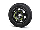 2009 Toyota Sienna Spare Wheel
 2009 Toyota Sienna CV Joint
 2009 Toyota Sienna Sway Bar Bushing
 2009 Toyota Sienna Bellhousing
 2009 Toyota Sienna CV Boot
 2009 Toyota Sienna Coil Spring Insulator
 2009 Toyota Sienna Control Arm Bushing
 2009 Toyota Sienna Differential Mount
 2009 Toyota Sienna Shock Absorber
 2009 Toyota Sienna Shock and Strut Boot
 2009 Toyota Sienna Steering Knuckle
 2009 Toyota Sienna Sway Bar Bracket