×
ToyotaParts- Hello
- Login or Register
- Quick Links
- Live Chat
- Track Order
- Parts Availability
- RMA
- Help Center
- Contact Us
- Shop for
- Toyota Parts
- Scion Parts
My Garage
My Account
Cart
OEM 2009 Toyota Matrix Axle Shaft
Car Axle Shaft- Select Vehicle by Model
- Select Vehicle by VIN
Select Vehicle by Model
orMake
Model
Year
Select Vehicle by VIN
For the most accurate results, select vehicle by your VIN (Vehicle Identification Number).
7 Axle Shafts found


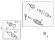
2009 Toyota Matrix Axle Assembly, Driver Side
Part Number: 43420-02B12$280.95 MSRP: $427.68You Save: $146.73 (35%)Product Specifications- Other Name: Shaft Assembly, Front Drive; CV Axle Assembly, Front Left; GSP Cv Axle; Axle Shaft; Axle; Shaft Assembly, Front Drive, Driver Side; CV Axle Assembly
- Position: Driver Side
- Replaces: 43420-02B11, 43420-02B10, 43420-02820, 43420-01110
- Part Name Code: 43420
- Item Weight: 15.80 Pounds
- Item Dimensions: 31.6 x 8.1 x 7.1 inches
- Condition: New
- Fitment Type: Direct Replacement
- SKU: 43420-02B12
- Warranty: This genuine part is guaranteed by Toyota's factory warranty.


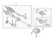
2009 Toyota Matrix Axle Assembly, Passenger Side
Part Number: 43410-02A03$308.77 MSRP: $467.38You Save: $158.61 (34%)Product Specifications- Other Name: Shaft Assembly, Front Drive; CV Axle Assembly, Front Right; GSP Cv Axle; Axle Shaft; Axle; Shaft Assembly, Front Drive, Passenger Side; CV Axle Assembly
- Position: Passenger Side
- Replaces: 43410-02760, 43410-02A02, 43410-01130, 43410-02A01, 43410-01131, 43410-02A00
- Part Name Code: 43410
- Item Weight: 20.20 Pounds
- Item Dimensions: 41.8 x 7.1 x 6.2 inches
- Condition: New
- Fitment Type: Direct Replacement
- SKU: 43410-02A03
- Warranty: This genuine part is guaranteed by Toyota's factory warranty.

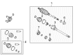
2009 Toyota Matrix Axle Assembly, Passenger Side
Part Number: 43410-01150$446.95 MSRP: $655.02You Save: $208.07 (32%)Ships in 1-3 Business DaysProduct Specifications- Other Name: Shaft Assembly, Front Drive; CV Axle Assembly, Front Right; GSP Cv Axle; Axle Shaft; Axle; Shaft Assembly, Front Drive, Passenger Side; CV Axle Assembly
- Position: Passenger Side
- Part Name Code: 43410
- Item Weight: 14.60 Pounds
- Item Dimensions: 29.8 x 7.5 x 6.4 inches
- Condition: New
- Fitment Type: Direct Replacement
- SKU: 43410-01150
- Warranty: This genuine part is guaranteed by Toyota's factory warranty.

2009 Toyota Matrix Axle Assembly, Passenger Side
Part Number: 43410-01140$446.95 MSRP: $655.02You Save: $208.07 (32%)Ships in 1-3 Business DaysProduct Specifications- Other Name: Shaft Assembly, Front Drive; CV Axle Assembly, Front Right; GSP Cv Axle; Axle Shaft; Axle; Shaft Assembly, Front Drive, Passenger Side; CV Axle Assembly
- Position: Passenger Side
- Part Name Code: 43410
- Item Weight: 14.80 Pounds
- Item Dimensions: 29.2 x 7.5 x 6.4 inches
- Condition: New
- Fitment Type: Direct Replacement
- SKU: 43410-01140
- Warranty: This genuine part is guaranteed by Toyota's factory warranty.

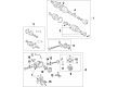
2009 Toyota Matrix Axle Assembly, Rear
Part Number: 42340-01010$378.62 MSRP: $554.88You Save: $176.26 (32%)Ships in 1-3 Business DaysProduct Specifications- Other Name: Shaft Assembly, Rear Drive; CV Axle Assembly, Rear Left, Rear Right; GSP Cv Axle; Axle Shaft; Shaft Assembly, Rear Drive, Passenger Side; Shaft Assembly, Rear Drive, Driver Side; CV Axle Assembly
- Position: Rear
- Item Weight: 15.30 Pounds
- Item Dimensions: 28.7 x 8.7 x 7.7 inches
- Condition: New
- Fitment Type: Direct Replacement
- SKU: 42340-01010
- Warranty: This genuine part is guaranteed by Toyota's factory warranty.
2009 Toyota Matrix Axle Assembly, Driver Side
Part Number: 43420-01130$400.76 MSRP: $587.32You Save: $186.56 (32%)Ships in 1-3 Business DaysProduct Specifications- Other Name: Shaft Assembly, Front Drive; CV Axle Assembly, Front Left; GSP Cv Axle; Axle Shaft; Axle; Shaft Assembly, Front Drive, Driver Side; CV Axle Assembly
- Position: Driver Side
- Part Name Code: 43420
- Item Weight: 14.80 Pounds
- Item Dimensions: 30.1 x 7.4 x 6.5 inches
- Condition: New
- Fitment Type: Direct Replacement
- SKU: 43420-01130
- Warranty: This genuine part is guaranteed by Toyota's factory warranty.
2009 Toyota Matrix Axle Assembly, Driver Side
Part Number: 43420-01120$400.76 MSRP: $587.32You Save: $186.56 (32%)Product Specifications- Other Name: Shaft Assembly, Front Drive; CV Axle Assembly, Front Left; GSP Cv Axle; Axle Shaft; Axle; Shaft Assembly, Front Drive, Driver Side; CV Axle Assembly
- Position: Driver Side
- Part Name Code: 43420
- Item Weight: 14.80 Pounds
- Item Dimensions: 29.2 x 7.6 x 6.7 inches
- Condition: New
- Fitment Type: Direct Replacement
- SKU: 43420-01120
- Warranty: This genuine part is guaranteed by Toyota's factory warranty.
2009 Toyota Matrix Axle Shaft
Looking for affordable OEM 2009 Toyota Matrix Axle Shaft? Explore our comprehensive catalogue of genuine 2009 Toyota Matrix Axle Shaft. All our parts are covered by the manufacturer's warranty. Plus, our straightforward return policy and speedy delivery service ensure an unparalleled shopping experience. We look forward to your visit!
2009 Toyota Matrix Axle Shaft Parts Q&A
- Q: How to remove and replace the axle shaft assembly on 2009 Toyota Matrix?A: Installation of the new front drive shaft hole snap ring LH starts with its placement opposite the front drive inboard joint assembly. Install the LH front drive shaft assembly using a brass bar and hammer to feed its inboard joint splines until the end gap of the front drive inboard joint hole snap ring rests downward without harming the oil seal or inboard joint boot. Verify proper drive shaft insertion by checking both a reaction force and listening for proper sound evidence. Using a screwdriver to install both 2WD and 4WD configuration front drive shaft assembly RH requires installation of a new bearing bracket hole snap ring and a new bolt with proper torque of 32 Nm (326 kgf-cm, 24 ft-lbf). A manual transmission case protector requires two bolts which need installation with 18 Nm torque (184 kgf-cm, 13 ft-lbf). Insert the front axle assembly LH into the vehicle while aligning its spline with the front axle assembly LH. Do this cautiously to prevent altering the outboard joint boot and speed sensor rotor dimensions. Adjust the front axle assembly RH using the identical method. The same procedures should be used to attach front lower suspension arms along with tie rod end sub-assemblies both to LH and RH sides during the installation of front suspension components for both 2WD and 4WD configurations. The front stabilizer link assemblies LH and RH must be connected while also installing the front speed sensors LH and RH. Apply non-residue solvent to all thread components on drive shaft and front axle shaft nut for cleaning purposes before installing the new axle shaft nut with a torque of 216 Nm (2203 kgf-cm, 159 ft-lbf) using a 30 mm socket wrench while manually hammer-staking the nut. Rephrase this step for installing the front axle shaft nut on the right-hand side. Install the front wheels as per specification of 103 Nm torque (1050 kgf-cm, 76 ft-lbf). Manual transaxle oil suits E351 while the vehicle needs automatic transaxle fluid for U140F and U250E as well as transfer oil for four-wheel drive. Examine E351 manual transaxle oil and U140F and U250E automatic transaxle fluid and additionally check for the transfer oil in 4WD systems. Adhere to installing the engine beneath LH and RH covers after performing examinations to control front wheel alignment adjustments. The completion of testing should include a check of speed sensor signals combined with VSC status assessment.
Related 2009 Toyota Matrix Parts
 2009 Toyota Matrix Axle Beam Mount
 2009 Toyota Matrix Bump Stop
 2009 Toyota Matrix Coil Spring Insulator
 2009 Toyota Matrix Coil Springs
 2009 Toyota Matrix Control Arm Bushing
 2009 Toyota Matrix Lateral Link
 2009 Toyota Matrix Shock Absorber
 2009 Toyota Matrix Shock And Strut Mount
 2009 Toyota Matrix Suspension Strut Rod
 2009 Toyota Matrix Sway Bar Bushing
 2009 Toyota Matrix Sway Bar Kit
 2009 Toyota Matrix Transfer Case Output Shaft Snap Ring