×
ToyotaParts- Hello
- Login or Register
- Quick Links
- Live Chat
- Track Order
- Parts Availability
- RMA
- Help Center
- Contact Us
- Shop for
- Toyota Parts
- Scion Parts
My Garage
My Account
Cart
OEM 2008 Toyota Solara Rack And Pinion
Steering Rack And Pinion- Select Vehicle by Model
- Select Vehicle by VIN
Select Vehicle by Model
orMake
Model
Year
Select Vehicle by VIN
For the most accurate results, select vehicle by your VIN (Vehicle Identification Number).
1 Rack And Pinion found

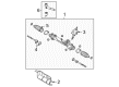
2008 Toyota Solara Steering Gear
Part Number: 44250-AA011$653.07 MSRP: $957.08You Save: $304.01 (32%)Ships in 1-3 Business DaysProduct Specifications- Other Name: Gear Assembly, Power Steering; Rack and Pinion Assembly; Steering Gearbox; Gear Assembly; Gear Assembly, Power Steering(For Rack & Pinion)
- Replaces: 44250-AA010
- Part Name Code: 44250
- Item Weight: 22.00 Pounds
- Item Dimensions: 41.0 x 13.5 x 7.2 inches
- Condition: New
- Fitment Type: Direct Replacement
- SKU: 44250-AA011
- Warranty: This genuine part is guaranteed by Toyota's factory warranty.
2008 Toyota Solara Rack And Pinion
Looking for affordable OEM 2008 Toyota Solara Rack And Pinion? Explore our comprehensive catalogue of genuine 2008 Toyota Solara Rack And Pinion. All our parts are covered by the manufacturer's warranty. Plus, our straightforward return policy and speedy delivery service ensure an unparalleled shopping experience. We look forward to your visit!
2008 Toyota Solara Rack And Pinion Parts Q&A
- Q: How to reassemble the power steering rack and pinion gear on 2008 Toyota Solara?A: The power steering rack and pinion assembly begins with an installation of the power steering fluid-coated O-ring on the rack and pinion followed by expansion and power steering fluid coating of the new oil seal before inserting it into the rack and pinion. A new cylinder tube oil seal lip should receive a coating of power steering fluid before installation using Special Service Tool: 09950-60010 09951-00420 with a press under correct orientation. Install the rack and pinion inside the rack housing after applying grease to the rack teeth ends and using Special Service Tool: 09631-33010 to secure it and coat the tool and power piston oil seal with power steering fluid. Install the rack bush into the rack housing by first coating a new O-ring with power steering fluid and afterwards using Special Service Tool: 09950-60010 09951-00400 to press install it. Then wrap the rack and pinion end with vinyl tape to prevent damage. Connect the rack housing slot to the installation hole of the cylinder end stopper wire while adding a new wire then rotate the stopper in a counterclockwise direction by 450 plus or minus 50°. Apply vacuum pressure of 53 kPa for 30 seconds through Special Service Tool: 09631-12071 while monitoring air pressure fluctuations. Install the upper oil seal with correct orientation using Special Service Tool: 09950-70010 09951-07150 and a press after coating it with power steering fluid and lubricating the control valve upper bearing. The control valve installation process requires extension of four new valve spacers next to the valve housing before covering them with power steering fluid and feeding Special Service Tool: 09631-20081 through them to install the control valve while guarding against damaging the spacers or oil seal lip. Start by coating a fresh oil seal lip with fluid from the power steering system then use Special Service Tool: 09612-22011 with a press to install it following the application of grease to both the needle roller bearing and the serrated part of the control valve before installation of a new gasket along with two bolts at 20 Nm attachment to the rack housing. The technician should utilize Special Service Tool: 09616-00011 to manage the control valve during new lock nut installation at 25 Nm with power steering fluid application to rack housing cap threads followed by socket wrench torque of 59 Nm for staking the components together. Start by spreading grease on the rack guide contact area then install it along with the compression spring followed by putting sealant on rack guide spring cap threads before fastening the cap temporarily. The rack guide spring cap requires torque to 25 Nm followed by loosening while adjusting the control valve before tightening until the preload reaches 1.2 to 1.5 Nm. Use Special Service Tool 09922-10010 to secure the rack guide spring cap lock nut at 51 Nm after applying sealant to its threads. The technician must check the total preload before removing the rack end sub-assemblies to apply MP grease on the control valve shaft then wrap the spline with vinyl tape before installing the dust cover. To install the rack and pinion end sub-assembly begin by installing two new claw washers before temporarily fitting both assemblies and securing them at 60 Nm torque using Special Service Tool: 09922-10010 followed by hammering the brass bar against the claw washers to stake them. Position the rack and pinion boots with their designated numerical order while applying silicon grease inside boot No. 2 before confirming proper installation without any injury to the components. Follow Special Service Tool: 09521-24010 to tighten clamps on both boots with a maximum opening of 3.0 mm. The tie rod assemblies need to be installed LH and RH with proper matchmark alignment followed by lock nut torque while toe-in needs adjustment. Use Special Service Tool: 09023-38201 to install both left and right turn pressure tubes at 11 Nm by positioning the tool parallel to the torque wrench then repeat installation.
Related 2008 Toyota Solara Parts
 2008 Toyota Solara Power Steering Pump
 2008 Toyota Solara Steering Wheel
 2008 Toyota Solara Drag Link
 2008 Toyota Solara Power Steering Control Valve
 2008 Toyota Solara Power Steering Hose
 2008 Toyota Solara Power Steering Reservoir
 2008 Toyota Solara Rack and Pinion Boot
 2008 Toyota Solara Steering Column
 2008 Toyota Solara Steering Column Cover
 2008 Toyota Solara Steering Gear Box
 2008 Toyota Solara Steering Shaft
 2008 Toyota Solara Tie Rod End