×
ToyotaParts- Hello
- Login or Register
- Quick Links
- Live Chat
- Track Order
- Parts Availability
- RMA
- Help Center
- Contact Us
- Shop for
- Toyota Parts
- Scion Parts
My Garage
My Account
Cart
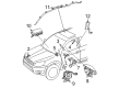
OEM 2008 Toyota RAV4 Air Bag
Air Bag Module- Select Vehicle by Model
- Select Vehicle by VIN
Select Vehicle by Model
orMake
Model
Year
Select Vehicle by VIN
For the most accurate results, select vehicle by your VIN (Vehicle Identification Number).
3 Air Bags found

2008 Toyota RAV4 Inflator Curtain, Driver Side
Part Number: 62180-0R010$721.87 MSRP: $1057.90You Save: $336.03 (32%)Ships in 1-3 Business DaysProduct Specifications- Other Name: Air Bag Assembly, Curtain Shield; Curtain Air Bag, Left; Head Air Bag; Air Bag Assembly, Curtain Shield, Driver Side
- Position: Driver Side
- Replaces: 62180-42040
- Part Name Code: 62180A
- Item Weight: 12.20 Pounds
- Item Dimensions: 47.4 x 18.9 x 9.3 inches
- Condition: New
- Fitment Type: Direct Replacement
- SKU: 62180-0R010
- Warranty: This genuine part is guaranteed by Toyota's factory warranty.
2008 Toyota RAV4 Inflator Curtain, Passenger Side
Part Number: 62170-0R010$721.87 MSRP: $1057.90You Save: $336.03 (32%)Ships in 1-3 Business DaysProduct Specifications- Other Name: Air Bag Assembly, Curtain Shield; Curtain Air Bag, Right; Head Air Bag; Air Bag Assembly, Curtain Shield, Passenger Side
- Position: Passenger Side
- Replaces: 62170-42050
- Part Name Code: 62170A
- Item Weight: 11.70 Pounds
- Item Dimensions: 46.4 x 18.4 x 9.4 inches
- Condition: New
- Fitment Type: Direct Replacement
- SKU: 62170-0R010
- Warranty: This genuine part is guaranteed by Toyota's factory warranty.

2008 Toyota RAV4 Passenger Air Bag, Upper
Part Number: 73960-0R012$634.34 MSRP: $929.63You Save: $295.29 (32%)Ships in 1-3 Business DaysProduct Specifications- Other Name: Air Bag Assembly, Instrument Panel; Instrument Panel Air Bag, Upper; Passenger Inflator Module; Air Bag Assembly, Instrument Panel Passenger W/O Door
- Position: Upper
- Replaces: 73960-0R010
- Part Name Code: 73960A
- Item Weight: 8.60 Pounds
- Item Dimensions: 14.9 x 11.7 x 8.0 inches
- Condition: New
- Fitment Type: Direct Replacement
- SKU: 73960-0R012
- Warranty: This genuine part is guaranteed by Toyota's factory warranty.
2008 Toyota RAV4 Air Bag
Looking for affordable OEM 2008 Toyota RAV4 Air Bag? Explore our comprehensive catalogue of genuine 2008 Toyota RAV4 Air Bag. All our parts are covered by the manufacturer's warranty. Plus, our straightforward return policy and speedy delivery service ensure an unparalleled shopping experience. We look forward to your visit!
2008 Toyota RAV4 Air Bag Parts Q&A
- Q: What are the essential precautions and procedures for handling Air Bag components in a Supplemental Restraint System on 2008 Toyota RAV4?A: Multiple safety features from the Supplemental Restraint System (SRS) are included in the vehicle such as the steering pad combined with the front passenger Air Bag and curtain shield Air Bag and front seat side Air Bag and seat belt pretensioner and center Air Bag sensor and front Air Bag sensor and side Air Bag sensor and rear Air Bag sensor and occupant classification ECU and seat position Air Bag sensor. Begin all service operations only after the ignition switch OFF and negative (-) battery terminal disconnect have elapsed a minimum 90 seconds. Hot air and fire must be avoided when working on SRS components while the technician must verify DTCs before disconnecting the negative (-) battery terminal because diagnosing system malfunctions can prove challenging. The inspection of SRS parts comes after minor collision events. The removal of Air Bag sensors must happen when controllers interfere with repair procedures. New SRS components must be used for all replacements because attempts to disassemble or repair these components should never happen. Always substitute the affected SRS component or piece with a new one after noticing damage or a drop incident. An ohmmeter/voltmeter with minimum impedance of 10 kOhms/V should be used for troubleshooting operations alongside the safe handling instructions found on the information labels of SRS parts. Execute the SRS warning light check following completion of work on SRS parts. The memory settings for each system should be recorded before working on the negative battery terminal while it is disconnected. The settings should be reset following completion of work. Yellow-colored SRS connectors maintain secure disconnect protection except for the seat position sensor and the occupant classification ECU connectors due to their default black coloration. Replace and adjust all components after disconnecting the negative (-) terminal cable by waiting for 90 seconds. Follow the precise procedures for sensor connector disconnection and connection by unlocking mechanisms under the direction of a screwdriver to achieve proper lockup with an audible click.
Related 2008 Toyota RAV4 Parts
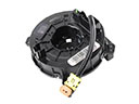 2008 Toyota RAV4 Clock Spring
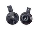 2008 Toyota RAV4 Horn
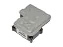 2008 Toyota RAV4 ABS Control Module
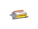 2008 Toyota RAV4 Air Bag Control Module
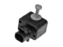 2008 Toyota RAV4 Air Bag Sensor
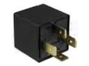 2008 Toyota RAV4 Daytime Running Light Relay
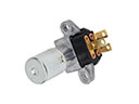 2008 Toyota RAV4 Dimmer Switch
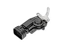 2008 Toyota RAV4 Door Lock Actuator Motor
 2008 Toyota RAV4 Hazard Warning Switch
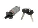 2008 Toyota RAV4 Ignition Lock Assembly
 2008 Toyota RAV4 Mirror Switch
 2008 Toyota RAV4 Neutral Safety Switch