×
ToyotaParts- Hello
- Login or Register
- Quick Links
- Live Chat
- Track Order
- Parts Availability
- RMA
- Help Center
- Contact Us
- Shop for
- Toyota Parts
- Scion Parts
My Garage
My Account
Cart
OEM 2008 Toyota Land Cruiser Camshaft
Cam- Select Vehicle by Model
- Select Vehicle by VIN
Select Vehicle by Model
orMake
Model
Year
Select Vehicle by VIN
For the most accurate results, select vehicle by your VIN (Vehicle Identification Number).
4 Camshafts found

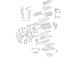
2008 Toyota Land Cruiser Camshaft
Part Number: 13501-38010$417.67 MSRP: $612.10You Save: $194.43 (32%)Ships in 1-3 Business DaysProduct Specifications- Other Name: Camshaft Sub-Assembly
- Replaces: 13501-0S010
- Part Name Code: 13511
- Item Weight: 4.30 Pounds
- Item Dimensions: 21.3 x 3.4 x 3.0 inches
- Condition: New
- Fitment Type: Direct Replacement
- SKU: 13501-38010
- Warranty: This genuine part is guaranteed by Toyota's factory warranty.

2008 Toyota Land Cruiser Camshaft
Part Number: 13502-38010$394.86 MSRP: $578.66You Save: $183.80 (32%)Ships in 1-3 Business DaysProduct Specifications- Other Name: Camshaft Sub-Assembly
- Replaces: 13502-0S010
- Part Name Code: 13512
- Item Weight: 4.30 Pounds
- Item Dimensions: 22.2 x 3.4 x 3.0 inches
- Condition: New
- Fitment Type: Direct Replacement
- SKU: 13502-38010
- Warranty: This genuine part is guaranteed by Toyota's factory warranty.

2008 Toyota Land Cruiser Camshaft Sub-Assembly
Part Number: 13054-38010$394.86 MSRP: $578.66You Save: $183.80 (32%)Ships in 1-3 Business DaysProduct Specifications- Other Name: Camshaft
- Replaces: 13054-0S010
- Part Name Code: 13054
- Item Weight: 4.80 Pounds
- Item Dimensions: 21.0 x 3.5 x 3.0 inches
- Condition: New
- Fitment Type: Direct Replacement
- SKU: 13054-38010
- Warranty: This genuine part is guaranteed by Toyota's factory warranty.

2008 Toyota Land Cruiser Camshaft Sub-Assembly
Part Number: 13053-38010$394.86 MSRP: $578.66You Save: $183.80 (32%)Ships in 1-3 Business DaysProduct Specifications- Other Name: Camshaft
- Replaces: 13053-0S010
- Part Name Code: 13053
- Item Weight: 4.40 Pounds
- Item Dimensions: 21.8 x 3.6 x 2.9 inches
- Condition: New
- Fitment Type: Direct Replacement
- SKU: 13053-38010
- Warranty: This genuine part is guaranteed by Toyota's factory warranty.
2008 Toyota Land Cruiser Camshaft
Looking for affordable OEM 2008 Toyota Land Cruiser Camshaft? Explore our comprehensive catalogue of genuine 2008 Toyota Land Cruiser Camshaft. All our parts are covered by the manufacturer's warranty. Plus, our straightforward return policy and speedy delivery service ensure an unparalleled shopping experience. We look forward to your visit!
2008 Toyota Land Cruiser Camshaft Parts Q&A
- Q: How to remove the camshaft on 2008 Toyota Land Cruiser?A: First work on the camshaft removal by discharging fuel system pressure followed by disconnecting the negative battery cable along with waiting 90 seconds to disable the SRS system. Start by taking off the upper radiator support seal then the radiator grille followed by removing the front bumper cover together with any required transmission oil cooler air duct. The technician disconnects radiator side deflectors followed by front fender main seals removal, then proceeds to remove wiper arms before extracting the hood to cowl top seal and cowl top ventilator louver sub-assembly and both front fender splash shield sub-assemblies. As the first step disassemble No. 1 and No. 2 engine undercovers following service with front fender apron seals then drain engine oil and coolant while taking out the V-bank cover sub-assembly along with air cleaner hose assembly and air cleaner assembly. The procedure demands the removal of No. 1 and No. 2 radiator hoses in addition to fan shroud and radiator assembly. Disconnection of engine wire occurs alongside the removal of air pump hose and wire harness and No. 2 water by-pass pipe and cooler compressor assembly and No. 2 fuel tube sub-assembly. The service technician must disconnect the oil filter element and other components like engine oil level dipstick guide, oil pressure sender gauge assembly and No. 1 oil cooler bracket together with the oil filter bracket in two configurations either with or without oil cooler and the intake manifold. The technician should detach the vane pump assembly along with the oil cooler pipe assembly, generator assembly, and both water by-pass hose and pipe sub-assembly and front water by-pass joint. The service requires disassembly of the front engine covers, air tube subsystem, water inlet housing with corresponding water pump pulley, No. 1 idler pulley subassembly along with fluid coupling bracket and V-ribbed belt tensioner assembly and ignition coil assembly and both cylinder head cover subassemblies. Start the procedure by taking out the spark plug tube gasket followed by the crankshaft pulley then the wire harness clamp bracket while also removing the timing chain cover sub-assembly and water inlet pipe. The No. 1 cylinder should be positioned at TDC/compression for the extraction of the No. 1 chain tensioner assembly, No. 1 chain tensioner slipper, No. 1 chain vibration damper, then remove the No. 1 chain sub-assembly, the No. 3 chain tensioner assembly, No. 1 chain tensioner assembly RH, No. 1 chain tensioner slipper RH, No. 1 chain vibration damper RH, No. 1 chain sub-assembly RH, and finally No. 2 chain tensioner assembly. After removing the crankshaft timing gear key perform the ordered sequence of cap bolt removal starting from the 10 then 18 bolts and finally the 6 bearing caps by uniformly loosening each bolt until complete removal and checking the correct positioning of the knock pin. Disassemble the engine by removing the No. 3 and No. 4 camshafts and afterward carefully prying off the camshaft housing sub-assembly LH. The procedure must also be applied to the camshaft bearing cap RH by correctly positioning the knock pin before bearing cap removal. Conclude the process by taking out the camshaft housing sub-assembly RH through the same prying method ensuring you protect both contact surfaces.
Related 2008 Toyota Land Cruiser Parts
 2008 Toyota Land Cruiser Cylinder Head
 2008 Toyota Land Cruiser Timing Chain
 2008 Toyota Land Cruiser Cam Gear
 2008 Toyota Land Cruiser Crankshaft Gear
 2008 Toyota Land Cruiser Crankshaft Pulley
 2008 Toyota Land Cruiser Crankshaft Seal
 2008 Toyota Land Cruiser Cylinder Head Gasket
 2008 Toyota Land Cruiser Dipstick Tube
 2008 Toyota Land Cruiser Exhaust Valve
 2008 Toyota Land Cruiser Oil Pan
 2008 Toyota Land Cruiser Piston Ring Set
 2008 Toyota Land Cruiser Rod Bearing