×
ToyotaParts- Hello
- Login or Register
- Quick Links
- Live Chat
- Track Order
- Parts Availability
- RMA
- Help Center
- Contact Us
- Shop for
- Toyota Parts
- Scion Parts
My Garage
My Account
Cart
OEM 2007 Toyota Yaris Rack And Pinion
Steering Rack And Pinion- Select Vehicle by Model
- Select Vehicle by VIN
Select Vehicle by Model
orMake
Model
Year
Select Vehicle by VIN
For the most accurate results, select vehicle by your VIN (Vehicle Identification Number).
1 Rack And Pinion found


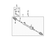
2007 Toyota Yaris Steering Gear
Part Number: 45510-52141$608.35 MSRP: $891.54You Save: $283.19 (32%)Ships in 1-2 Business DaysProduct Specifications- Other Name: Gear Assembly, Steering; Rack and Pinion Assembly; Steering Gearbox; Gear Assembly
- Replaces: 45510-52140
- Part Name Code: 45510
- Condition: New
- Fitment Type: Direct Replacement
- SKU: 45510-52141
- Warranty: This genuine part is guaranteed by Toyota's factory warranty.
2007 Toyota Yaris Rack And Pinion
Looking for affordable OEM 2007 Toyota Yaris Rack And Pinion? Explore our comprehensive catalogue of genuine 2007 Toyota Yaris Rack And Pinion. All our parts are covered by the manufacturer's warranty. Plus, our straightforward return policy and speedy delivery service ensure an unparalleled shopping experience. We look forward to your visit!
2007 Toyota Yaris Rack And Pinion Parts Q&A
- Q: How to service and repair the power Rack And Pinion for the sedan on 2007 Toyota Yaris?A: Begin the power steering rack and pinion repair and service on the sedan through wheel alignment with straight wheels then moving forward with battery cable removal from the negative terminal. Proceed to service the power steering rack and pinion by first removing the 4 bolts securing the hood then removing the head cap from the front wiper arms and next removing the left and right front wiper arm and blade assemblies one by one. The service requires removal of the left and right cowl side ventilator sub-assemblies together with the cowl top ventilator louver sub-assembly followed by the front wiper motor and link and front air shutter seal and cowl top panel outer. The silencer sheet should be removed from the column hole after uninstalling floor carpet and unfastening two clips. Use a seat belt to secure the steering wheel while maintaining the spiral cable safety and place marks on the slide yoke before loosely installing bolt A and removing bolt B to split the steering intermediate shaft. To begin disassembly proceed by removing clip A from the No. 1 steering column hole cover then separate clip B. The front wheel, left and right tie rod end sub-assemblies and left and right front stabilizer link assemblies need removal followed by left and right front suspension lower arms. Mount the engine by unscrewing the radio setting condenser bolt together with the air-fuel ratio sensor wiring bracket bolt and then install the engine hanger (Part No.: 12281-21010) at a torque of 40 N m (408 kgf cm, 30 ft. lbf) using bolt (Part No.: 91642-81025). Provide support for the engine assembly with engine sling and chain block before removing the front suspension crossmember sub-assembly when the engine moving control rod bolt was detached and the transmission jack provided support for the process of removing 6 bolts. The power steering rack and pinion removal requires extracting two bolts and two nuts from their locations without permitting the nut to turn. After placement of the power steering rack and pinion onto the front suspension crossmember use two bolts and two nuts to complete installation while maintaining the nut stationary. The fastener torque should be set to 96 N m (979 kgf cm, 71 ft. lbf). Attach the front suspension crossmember sub-assembly temporarily with its 6 bolts before tightening bolts A, B, and C to specified torques using Special Service Tool: 09670-00011 reaching 70 N m (714 kgf cm, 52 ft. lbf), 160 N m (1,631 kgf cm, 118 ft. lbf) and 95 N m (969 kgf cm, 70 ft. lbf) respectively. The technician should first install the front moving control rod reaching 120 N m (1,224 kgf cm, 89 ft. lbf) torque before securing the front suspension lower arms and front stabilizer link assemblies and tie rod end sub-assemblies on both sides. Reinstall the front wheel at 103 N m (1,050 kgf cm, 76 ft. lbf) before installing the No. 1 steering column hole cover sub-assembly without damaging its lip. The steering sliding yoke sub-assembly requires installation with a torque value of 28 N m (290 kgf cm, 21 ft. lbf) after aligning the matchmarks. The installation process begins with the column hole cover silencer sheet and floor carpet before adding the cowl top panel outer, front air shutter seal, windshield wiper motor and link, cowl top ventilator louver sub-assembly and both left and right cowl side ventilator sub-assemblies, left and right front wiper arm and blade assemblies, and concludes with the front wiper arm head cap. Use 4 bolts to provisionally fasten the hood sub-assembly while performing an inspection of the hood followed by reconnecting the cable to the negative battery terminal with a torque specification of 5.4 N m (55 kgf cm, 48 ft. lbf) before adjusting the alignment of the front wheels as well as performing ABS speed sensor signal assessment.
Related 2007 Toyota Yaris Parts
 2007 Toyota Yaris Steering Column
 2007 Toyota Yaris Steering Wheel
 2007 Toyota Yaris Ignition Switch
 2007 Toyota Yaris Rack and Pinion Boot
 2007 Toyota Yaris Shift Interlock Solenoid
 2007 Toyota Yaris Steering Column Cover
 2007 Toyota Yaris Steering Gear Box
 2007 Toyota Yaris Steering Shaft
 2007 Toyota Yaris Tie Rod End
 2007 Toyota Yaris Wiper Switch