×
ToyotaParts- Hello
- Login or Register
- Quick Links
- Live Chat
- Track Order
- Parts Availability
- RMA
- Help Center
- Contact Us
- Shop for
- Toyota Parts
- Scion Parts
My Garage
My Account
Cart
OEM 2007 Toyota Tundra Antenna
Radio Antenna- Select Vehicle by Model
- Select Vehicle by VIN
Select Vehicle by Model
orMake
Model
Year
Select Vehicle by VIN
For the most accurate results, select vehicle by your VIN (Vehicle Identification Number).
2 Antennas found


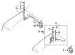
2007 Toyota Tundra Antenna Mast
Part Number: 86309-0C020$38.11 MSRP: $51.41You Save: $13.30 (26%)Ships in 1-3 Business DaysProduct Specifications- Other Name: Pole Sub-Assembly, Pull; Radio Antenna Assembly; Radio Antenna Mast; Antenna Assembly; Mast; Pole Sub-Assembly, Pull Top Antenna
- Replaces: 86309-42060, 86309-AA040, 86309-AA041, 86309-35100, 86309-42040, 86309-42041, 86309-AA042
- Part Name Code: 86309B
- Item Weight: 2.40 Pounds
- Item Dimensions: 36.4 x 4.2 x 4.2 inches
- Condition: New
- Fitment Type: Direct Replacement
- SKU: 86309-0C020
- Warranty: This genuine part is guaranteed by Toyota's factory warranty.


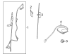
2007 Toyota Tundra Antenna Base
Part Number: 86309-0C040$41.45 MSRP: $55.93You Save: $14.48 (26%)Ships in 1-2 Business DaysProduct Specifications- Other Name: Pole Sub-Assembly, Pillar; Radio Antenna Base; Base; Pole Sub-Assembly, Pillar Antenna
- Part Name Code: 86309
- Item Weight: 1.40 Pounds
- Item Dimensions: 15.9 x 11.4 x 3.2 inches
- Condition: New
- Fitment Type: Direct Replacement
- SKU: 86309-0C040
- Warranty: This genuine part is guaranteed by Toyota's factory warranty.
2007 Toyota Tundra Antenna
Looking for affordable OEM 2007 Toyota Tundra Antenna? Explore our comprehensive catalogue of genuine 2007 Toyota Tundra Antenna. All our parts are covered by the manufacturer's warranty. Plus, our straightforward return policy and speedy delivery service ensure an unparalleled shopping experience. We look forward to your visit!
2007 Toyota Tundra Antenna Parts Q&A
- Q: How to service the radio antenna on 2007 Toyota Tundra?A: Attention must be paid to initialization requirements since reconnecting the cable will service the radio antenna. Maintain an at least 90-second pause with the ignition switch OFF before removing the cable to ensure the navigation system correctly stores all information. The service begins with removing the antenna ornament followed by taking off the right-hand fender apron mudguard seal. Start by removing the connector connecting the fender antenna assembly then remove the bolt while detaching the five clamps to uninstall the antenna. Start by securing the fender antenna assembly with the bolt followed by re-clamping five points before restating the bolt and connector. After the fender apron mudguard seal on the right-hand side and the antenna ornament should be installed. Before concluding the installation step reconnect the cable to the negative battery terminal although initialization procedures might be needed for specific systems.
Related 2007 Toyota Tundra Parts
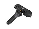 2007 Toyota Tundra TPMS Sensor
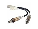 2007 Toyota Tundra Oxygen Sensor
 2007 Toyota Tundra Camshaft Position Sensor
 2007 Toyota Tundra Oil Pressure Gauge
 2007 Toyota Tundra Spark Plug
 2007 Toyota Tundra Speedometer
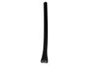 2007 Toyota Tundra Antenna Mast
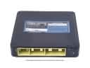 2007 Toyota Tundra Engine Control Module
 2007 Toyota Tundra Body Control Module
 2007 Toyota Tundra Car Key
 2007 Toyota Tundra Hazard Warning Switch
 2007 Toyota Tundra Transmitter