×
ToyotaParts- Hello
- Login or Register
- Quick Links
- Live Chat
- Track Order
- Parts Availability
- RMA
- Help Center
- Contact Us
- Shop for
- Toyota Parts
- Scion Parts
My Garage
My Account
Cart
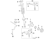
OEM 2007 Toyota Tacoma Wheel Hub
Wheel Axle Hub- Select Vehicle by Model
- Select Vehicle by VIN
Select Vehicle by Model
orMake
Model
Year
Select Vehicle by VIN
For the most accurate results, select vehicle by your VIN (Vehicle Identification Number).
5 Wheel Hubs found


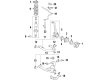
2007 Toyota Tacoma Front Hub
Part Number: 43502-04080$165.31 MSRP: $234.02You Save: $68.71 (30%)Ships in 1-3 Business DaysProduct Specifications- Other Name: Hub Sub-Assembly, Front Axle; Wheel Hub, Front; Wheel Hub Repair Kit; Wheel Hub Assembly; Hub; Hub Sub-Assembly, Front Axle, Passenger Side; Hub Sub-Assembly, Front Axle, Driver Side; Wheel Hub
- Position: Front
- Replaces: 43502-04120
- Item Weight: 4.10 Pounds
- Condition: New
- Fitment Type: Direct Replacement
- SKU: 43502-04080
- Warranty: This genuine part is guaranteed by Toyota's factory warranty.


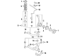
2007 Toyota Tacoma Wheel Hub, Front
Part Number: 43502-04140$176.95 MSRP: $252.65You Save: $75.70 (30%)Ships in 1-3 Business DaysProduct Specifications- Other Name: Hub Sub-Assembly, Front Axle; Wheel Hub, Front; Wheel Hub Repair Kit; Front Hub; Hub; Hub Sub-Assembly, Front Axle, Passenger Side; Hub Sub-Assembly, Front Axle, Driver Side
- Position: Front
- Replaces: 43502-04130
- Item Weight: 6.50 Pounds
- Item Dimensions: 11.6 x 8.4 x 5.2 inches
- Condition: New
- Fitment Type: Direct Replacement
- SKU: 43502-04140
- Warranty: This genuine part is guaranteed by Toyota's factory warranty.


2007 Toyota Tacoma Front Hub
Part Number: 43502-04112$173.07 MSRP: $245.00You Save: $71.93 (30%)Ships in 1-3 Business DaysProduct Specifications- Other Name: Hub Sub-Assembly, Front Axle; Wheel Hub, Front; Wheel Hub Repair Kit; Hub; Hub Sub-Assembly, Front Axle, Passenger Side; Hub Sub-Assembly, Front Axle, Driver Side; Wheel Hub
- Position: Front
- Replaces: 43502-35230
- Item Weight: 10.80 Pounds
- Item Dimensions: 12.4 x 12.2 x 6.8 inches
- Condition: New
- Fitment Type: Direct Replacement
- SKU: 43502-04112
- Warranty: This genuine part is guaranteed by Toyota's factory warranty.


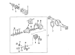
2007 Toyota Tacoma Bearing Housing, Passenger Side
Part Number: 42450-04010$356.15 MSRP: $521.95You Save: $165.80 (32%)Product Specifications- Other Name: Bearing Assembly, Rear Axle; Wheel Bearing & Hub; Wheel Hub Repair Kit; Axle Bearing; Rear Hub & Bearing; Hub & Bearing; Hub & Bearing Assembly, Rear Axle, Passenger Side
- Position: Passenger Side
- Part Name Code: 42450A
- Item Weight: 6.60 Pounds
- Item Dimensions: 6.1 x 6.1 x 4.6 inches
- Condition: New
- Fitment Type: Direct Replacement
- SKU: 42450-04010
- Warranty: This genuine part is guaranteed by Toyota's factory warranty.


2007 Toyota Tacoma Bearing Housing, Driver Side
Part Number: 42460-04010$356.15 MSRP: $521.95You Save: $165.80 (32%)Product Specifications- Other Name: Bearing Assembly, Rear Axle; Wheel Bearing & Hub; Wheel Hub Repair Kit; Axle Bearing; Hub Assembly; Rear Hub & Bearing; Hub & Bearing; Hub & Bearing Assembly, Rear Axle, Driver Side
- Position: Driver Side
- Part Name Code: 42450B
- Item Weight: 9.00 Pounds
- Item Dimensions: 7.0 x 6.6 x 5.0 inches
- Condition: New
- Fitment Type: Direct Replacement
- SKU: 42460-04010
- Warranty: This genuine part is guaranteed by Toyota's factory warranty.
2007 Toyota Tacoma Wheel Hub
Looking for affordable OEM 2007 Toyota Tacoma Wheel Hub? Explore our comprehensive catalogue of genuine 2007 Toyota Tacoma Wheel Hub. All our parts are covered by the manufacturer's warranty. Plus, our straightforward return policy and speedy delivery service ensure an unparalleled shopping experience. We look forward to your visit!
2007 Toyota Tacoma Wheel Hub Parts Q&A
- Q: How to service and repair the front Wheel Hub on 2007 Toyota Tacoma?A: The Service and Repair process for the front axle hub starts with disconnecting battery cable from terminal and wheel removal followed by disconnecting the speed sensor wire and removing its 2 connecting bolts. Remove the front speed sensor while extracting its bolt and then separate the front flexible hose by dismantling the bolt. The front disc brake caliper assembly removal starts by detaching the flexible hose following removal of the union bolt and gasket and continues with taking out the 2 bolts to remove the brake caliper. The procedure starts with disc removal and continued with the separation of the tie rod end sub-assembly by removing the cotter pin and nut before using SST 09610-20012 to disconnect the tie rod end from the steering knuckle arm. Separate the front suspension lower arm by first removing its 2 bolts to detach the front lower ball joint from the front axle and for the upper arm separate it from the steering knuckle with SST 09628-62011 after removing the clip and nut. To disassemble the knuckle grease retainer cap requires a screwdriver and a hammer to remove it. Then use SST 09930-00010 to loosen the staked part of the lock nut before using a socket wrench (36 mm) to remove it after fixing the hub into a vice which uses 3 bolts. Start by removing three bolts from the steering knuckle followed by moving the dust cover before using SST 09710-30021 (09710-03131) to separate the knuckle from the dust protector. Pray open the front axle hub oil seal with a screwdriver before you pull out the inner bearing by using snap ring pliers with SST 09950-60020 (09951-00710) and 09950-70010 (09951-07150). An inner bearing can be installed into the steering knuckle through SST 09527-17011 and 09608-10010 before adding a new snap ring. Start by installing a new oil seal through SST 09223-15020 and 09527-17011 tools while applying MP grease on the seal lip. Fasten the dust cover onto the steering knuckle using 3 bolts which should be torqued to 8.3 Nm (85 kgf-cm, 73 inch lbs.). Then use SST 09710-30050 to press in the axle hub properly. After fixing the axle hub in a vice you should install a new lock nut and torque it to 199 Nm (2,029 kgf-cm, 147 ft. lbs.) then stake it with a chisel and hammer. Users must handle the knuckle grease retainer cap with care to prevent destruction. Place the front axle hub followed by installing the front suspension upper arm with its new nut and torque to 110 Nm (1,122 kgf-cm, 81 ft. lbs.). Install the clip while aligning its holes. Use two bolts to install the front lower ball joint attachment LH before torquing them to 160 Nm (1,631 kgf-cm, 118 ft. lbs.). Subsequently install the tie rod end onto the steering knuckle arm and fasten it with a new cotter pin and nut that needs torquing to 49 Nm (500 kgf-cm, 36 ft. lbs.). First install the front disc brake components via 2 bolts that need 108 Nm (1,101 kgf-cm, 80 ft. lbs.) tightening before implementing a new gasket and flexible hose attaching to a union bolt, which requires 30 Nm (306 kgf-cm, 22 ft. lbs.) torque. Thread and bolt the front flexible hose before torquing to 32 Nm (326 kgf-cm, 24 ft. lbs.) and install the front speed sensor using the bolt with 8.3 Nm (85 kgf-cm, 73 inch lbs.) while keeping the sensor tip clean. Finally, install the skid control sensor wire with 2 bolts, torquing to 5.0 Nm (51 kgf-cm, 44 inch lbs.), connect the speed sensor connector, install the front wheel with a torque of 113 Nm (1,152 kgf-cm, 83 ft. lbs.), reconnect the cable to the negative battery terminal with a torque of 3.9 Nm (40 kgf-cm, 35 inch lbs.), fill the reservoir with brake fluid, bleed the master cylinder and brake lines as necessary, check fluid levels, inspect for leaks, and check the VSC and ABS sensor signals, concluding with an inspection and adjustment of the front wheel alignment.
Related 2007 Toyota Tacoma Parts
 2007 Toyota Tacoma Wheel Bearing
 2007 Toyota Tacoma Brake Disc
 2007 Toyota Tacoma Brake Caliper
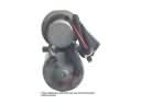 2007 Toyota Tacoma ABS Pump And Motor Assembly
 2007 Toyota Tacoma Backing Plate
 2007 Toyota Tacoma Brake Drum
 2007 Toyota Tacoma Brake Shoe Set
 2007 Toyota Tacoma Parking Brake Shoe
 2007 Toyota Tacoma Spindle Nut
 2007 Toyota Tacoma Wheel Cylinder
 2007 Toyota Tacoma Wheel Stud
 2007 Toyota Tacoma Yaw Sensor