×
ToyotaParts- Hello
- Login or Register
- Quick Links
- Live Chat
- Track Order
- Parts Availability
- RMA
- Help Center
- Contact Us
- Shop for
- Toyota Parts
- Scion Parts
My Garage
My Account
Cart
OEM 2007 Toyota FJ Cruiser Shock Absorber
Suspension Shock Absorber- Select Vehicle by Model
- Select Vehicle by VIN
Select Vehicle by Model
orMake
Model
Year
Select Vehicle by VIN
For the most accurate results, select vehicle by your VIN (Vehicle Identification Number).
4 Shock Absorbers found


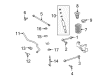
2007 Toyota FJ Cruiser Shock Absorber
Part Number: 48530-80460$63.03 MSRP: $88.48You Save: $25.45 (29%)Ships in 1-3 Business DaysProduct Specifications- Other Name: Absorber Set, Shock; Rear Shock Absorber; Suspension Kit; Strut Assembly; Complete Strut; Shock; Absorber Assembly, Shock, Rear Passenger Side; Absorber Assembly, Shock, Rear Driver Side
- Manufacturer Note: MARK 48530-35121
- Replaces: 48530-80354
- Item Weight: 6.50 Pounds
- Item Dimensions: 26.1 x 6.8 x 5.9 inches
- Condition: New
- Fitment Type: Direct Replacement
- SKU: 48530-80460
- Warranty: This genuine part is guaranteed by Toyota's factory warranty.


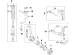
2007 Toyota FJ Cruiser Shock Absorber
Part Number: 48510-80397$145.92 MSRP: $206.58You Save: $60.66 (30%)Ships in 1-2 Business DaysProduct Specifications- Other Name: Absorber Set, Shock; Suspension Kit; Strut Assembly; Shock Absorber; Strut Kit; Complete Strut; Strut; Absorber Assembly, Shock, Front Passenger Side; Absorber Assembly, Shock, Front Driver Side; Shock
- Manufacturer Note: MARK 48510-35271
- Replaces: 48510-80315
- Item Weight: 1.40 Pounds
- Item Dimensions: 26.4 x 8.4 x 7.5 inches
- Condition: New
- Fitment Type: Direct Replacement
- SKU: 48510-80397
- Warranty: This genuine part is guaranteed by Toyota's factory warranty.
2007 Toyota FJ Cruiser Shock Absorber
Part Number: 48530-80461$63.03 MSRP: $88.48You Save: $25.45 (29%)Ships in 1-2 Business DaysProduct Specifications- Other Name: Absorber Set, Shock; Rear Shock Absorber; Suspension Kit; Strut Assembly; Complete Strut; Shock; Absorber Assembly, Shock, Rear Passenger Side; Absorber Assembly, Shock, Rear Driver Side
- Manufacturer Note: MARK 48530-35111
- Replaces: 48530-80355
- Item Weight: 1.40 Pounds
- Item Dimensions: 25.8 x 6.7 x 5.8 inches
- Condition: New
- Fitment Type: Direct Replacement
- SKU: 48530-80461
- Warranty: This genuine part is guaranteed by Toyota's factory warranty.

2007 Toyota FJ Cruiser Shock Absorber
Part Number: 48510-80396$134.76 MSRP: $190.77You Save: $56.01 (30%)Ships in 1-3 Business DaysProduct Specifications- Other Name: Absorber Set, Shock; Suspension Kit; Strut Assembly; Shock Absorber; Strut Kit; Complete Strut; Strut; Absorber Assembly, Shock, Front Passenger Side; Absorber Assembly, Shock, Front Driver Side; Shock
- Manufacturer Note: MARK 48510-35281
- Replaces: 48510-80314
- Item Weight: 9.80 Pounds
- Item Dimensions: 27.1 x 8.3 x 7.6 inches
- Condition: New
- Fitment Type: Direct Replacement
- SKU: 48510-80396
- Warranty: This genuine part is guaranteed by Toyota's factory warranty.
2007 Toyota FJ Cruiser Shock Absorber
Looking for affordable OEM 2007 Toyota FJ Cruiser Shock Absorber? Explore our comprehensive catalogue of genuine 2007 Toyota FJ Cruiser Shock Absorber. All our parts are covered by the manufacturer's warranty. Plus, our straightforward return policy and speedy delivery service ensure an unparalleled shopping experience. We look forward to your visit!
2007 Toyota FJ Cruiser Shock Absorber Parts Q&A
- Q: How to service the rear shock absorber on 2007 Toyota FJ Cruiser?A: Service of the rear shock absorber begins by removing the rear wheel. After supporting the rear axle housing position you need to remove the bolt to divide the shock absorber. You must first prevent the piston rod from turning before removing the three cushion retainers along with the nut and extracting the shock absorber, No. 1 cushion, No. 2 cushion. The installation of a new shock absorber becomes necessary when you find irregular resistance or unusual sounds while pressing or extending the rod during inspection of the rear shock absorber. The three cushion retainers together with No. 1 cushion and No. 2 cushion and new nut must be installed onto the rear shock absorber before tightening it temporarily. Then proceed with shock absorber bolt installation. Tighten the new nut by rotating it to 25 N m (255 kgf cm, 18 ft. lbf) while gripping the piston rod. Install the rear wheel with 112 N m torque, which is equivalent to 1,137 kgf cm or 82 ft. lbf. You must stabilize the suspension through vehicle jacking and bouncing it multiple times. Complete tightening of the rear shock absorber bolt needs to be performed at 98 N m (1,000 kgf cm, 72 ft. lbf). To discard the shock absorber open the piston rod completely before drilling a hole on the cylinder to release the gas inside while keeping the drill blade covered with a shop rag or cloth since the released gas is neither colored nor scented nor dangerous.
Related 2007 Toyota FJ Cruiser Parts
 2007 Toyota FJ Cruiser Coil Springs
 2007 Toyota FJ Cruiser Alignment Bolt
 2007 Toyota FJ Cruiser Ball Joint
 2007 Toyota FJ Cruiser Bump Stop
 2007 Toyota FJ Cruiser Control Arm
 2007 Toyota FJ Cruiser Control Arm Bushing
 2007 Toyota FJ Cruiser Lateral Link
 2007 Toyota FJ Cruiser Shock And Strut Mount
 2007 Toyota FJ Cruiser Steering Knuckle
 2007 Toyota FJ Cruiser Sway Bar Bracket
 2007 Toyota FJ Cruiser Sway Bar Bushing
 2007 Toyota FJ Cruiser Sway Bar Kit