×
ToyotaParts- Hello
- Login or Register
- Quick Links
- Live Chat
- Track Order
- Parts Availability
- RMA
- Help Center
- Contact Us
- Shop for
- Toyota Parts
- Scion Parts
My Garage
My Account
Cart
OEM 2007 Toyota FJ Cruiser Camshaft
Cam- Select Vehicle by Model
- Select Vehicle by VIN
Select Vehicle by Model
orMake
Model
Year
Select Vehicle by VIN
For the most accurate results, select vehicle by your VIN (Vehicle Identification Number).
4 Camshafts found

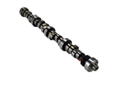
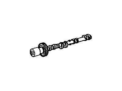
2007 Toyota FJ Cruiser Camshaft
Part Number: 13501-31040$547.97 MSRP: $803.06You Save: $255.09 (32%)Ships in 1-3 Business DaysProduct Specifications- Other Name: Camshaft Sub-Assembly
- Part Name Code: 13511
- Item Weight: 4.30 Pounds
- Item Dimensions: 22.4 x 3.5 x 2.9 inches
- Condition: New
- Fitment Type: Direct Replacement
- SKU: 13501-31040
- Warranty: This genuine part is guaranteed by Toyota's factory warranty.
2007 Toyota FJ Cruiser Camshaft
Part Number: 13502-31010$547.97 MSRP: $803.06You Save: $255.09 (32%)Ships in 1-3 Business DaysProduct Specifications- Other Name: Camshaft Sub-Assembly
- Part Name Code: 13512
- Item Weight: 4.40 Pounds
- Item Dimensions: 22.4 x 3.4 x 2.9 inches
- Condition: New
- Fitment Type: Direct Replacement
- SKU: 13502-31010
- Warranty: This genuine part is guaranteed by Toyota's factory warranty.
2007 Toyota FJ Cruiser Camshaft
Part Number: 13054-31010$547.97 MSRP: $803.06You Save: $255.09 (32%)Ships in 1-3 Business DaysProduct Specifications- Other Name: Camshaft Sub-Assembly
- Part Name Code: 13054
- Item Weight: 4.90 Pounds
- Item Dimensions: 22.0 x 3.4 x 2.9 inches
- Condition: New
- Fitment Type: Direct Replacement
- SKU: 13054-31010
- Warranty: This genuine part is guaranteed by Toyota's factory warranty.
2007 Toyota FJ Cruiser Camshaft
Part Number: 13053-31010$547.97 MSRP: $803.06You Save: $255.09 (32%)Ships in 1-3 Business DaysProduct Specifications- Other Name: Camshaft Sub-Assembly
- Part Name Code: 13053
- Item Weight: 4.80 Pounds
- Item Dimensions: 21.4 x 3.5 x 3.0 inches
- Condition: New
- Fitment Type: Direct Replacement
- SKU: 13053-31010
- Warranty: This genuine part is guaranteed by Toyota's factory warranty.
2007 Toyota FJ Cruiser Camshaft
Looking for affordable OEM 2007 Toyota FJ Cruiser Camshaft? Explore our comprehensive catalogue of genuine 2007 Toyota FJ Cruiser Camshaft. All our parts are covered by the manufacturer's warranty. Plus, our straightforward return policy and speedy delivery service ensure an unparalleled shopping experience. We look forward to your visit!
2007 Toyota FJ Cruiser Camshaft Parts Q&A
- Q: How to install the No. 3 camshaft sub-assembly on 2007 Toyota FJ Cruiser?A: When putting together the No. 3 camshaft sub-assembly maintain the camshaft horizontal position to safeguard the cylinder head journal surface. Apply engine oil to both camshafts before positioning the yellow mark link at the 2 dot timing marks of the camshaft timing gear. Then temporarily place the No. 1 chain on the No. 2 chain positions. Place the camshaft timing gear knock pin hole alongside the No. 3 camshaft knock pin and use it to insert into the camshaft timing gear. Then install the camshaft timing gear set bolt for temporary service. Install and align the No. 3 camshaft with its No. 2 cylinder lobes pointing downward on bank 2 head while putting bearing caps where they belong and giving bearing cap bolts light engine oil treatment on threads and under their heads. A multi-step process should be used to install the 8 bearing cap bolts evenly applying 10 mm (0.39 in.) head torque of 9.0 N m (92 kgf cm, 80 in. lbf.) and 12 mm (0.47 in.) head torque of 24 N m (245 kgf cm, 18 ft. lbf.). Tighten the camshaft timing gear set bolt to 100 N m (1,020 kgf cm, 74 ft. lbf) after correctly positioning the hexagonal part of No. 3 camshaft with a wrench while aligning the No. 1 chain paint mark with the timing gear marks. Tear the tensioner to expose its opening then insert a 1.0 mm (0.039 in.) wide holding pin during which you should put in place the camshaft timing gear together with the No. 3 chain tensioner assembly with yellow mark links pointed toward the specified timing marks and tighten the No. 3 chain tensioner bolt to 19 N m (194 kgf cm, 14 ft. lbf.). Use the same procedures for the No. 4 camshaft sub-assembly while maintaining level orientation and aligning the knock pin hole with the camshaft before installing the camshaft timing gear set bolt temporarily and tightening the 4 bearing caps with oil application on the bearing cap bolts following sequence torque specifications. Unscrew and extract the No. 3 chain tensioner pin while letting the chain tension automatically relax. Place the yellow-marked chain link beside the 1 dot timing mark before you apply new engine oil and position the No.1 chain temporary onto the No.2 chain. Add the knock pin hole to the No.1 camshaft and place it into the camshaft timing gear. Secure the No. 1 camshaft into the bank 1 cylinder head with cam lobe pointing downwards while installing 4 bearing caps then lubricate bearing cap bolts before tightening them in correct order. When the camshaft timing marks are aligned rotate the No. 1 camshaft clockwise before installing a wrench to the hexagonal portion to finally tighten the camshaft timing gear set bolt to 100 N m (1,020 kgf cm, 74 ft. lbf.). The process of installing the No. 2 chain tensioner assembly involves pushing the tensioner while inserting a 1.0 mm (0.039 in.) pin followed by temporarily mounting both the camshaft timing gear and No. 2 chain tensioner and tightening the No. 2 chain tensioner bolt to 19 N m (194 kgf cm, 14 ft. lbf). Complete the installation of the bank 1 cylinder head No. 2 camshaft by facing its cam lobes upwards while adding engine oil to bearing cap bolts before securing them in a proper sequence. After aligning the knock pin through clockwise rotation of the No. 2 camshaft, hold it securely with a wrench to install the camshaft timing gear set bolt with a torque value of 100 N m (1,020 kgf cm, 74 ft. lbf.). The procedure for the No. 1 chain tensioner assembly includes pushing in the plunger while turning the stopper plate clockwise and then securing the stopper plate with a 3.5 mm (0.138 in.) bar and finally attaching the tensioner with 2 bolts tightened to 10 N m (102 kgf cm, 7.4 ft. lbf.) and removing the bar. Wipe the timing marks clean and screw in the new gasket with time chain cover plate using 4 bolts at 9.0 N m (92 kgf cm, 80 in. lbf.). Align the crankshaft pulley at the "0" timing mark after rotating the pulley for 2 revolutions. Then check all timing marks for alignment. The installation begins with setting the cylinder to TDC/compression followed by valve clearance inspection and ends with the LH cylinder head cover sub-assembly installation through removal of old packing followed by diameter 2 to 3 mm (0.08 to 0.12 in.) seal packing application and adding seal washers before tightening with specified torque values on 10 bolts and 2 nuts. To complete the installation you need to put on the ignition coil assembly and intake air surge tank followed by surge tank stays then add the oil baffle plate before fixing the throttle body bracket and air cleaner assembly while you connect the negative battery terminal at 3.9 N m (40 kgf cm, 35 in. lbf.) and fill engine with coolant before leak and ignition timing inspections and finally the V-bank cover installation.
