×
ToyotaParts- Hello
- Login or Register
- Quick Links
- Live Chat
- Track Order
- Parts Availability
- RMA
- Help Center
- Contact Us
- Shop for
- Toyota Parts
- Scion Parts
My Garage
My Account
Cart
OEM 2007 Toyota Camry Antenna
Radio Antenna- Select Vehicle by Model
- Select Vehicle by VIN
Select Vehicle by Model
orMake
Model
Year
Select Vehicle by VIN
For the most accurate results, select vehicle by your VIN (Vehicle Identification Number).
4 Antennas found


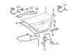
2007 Toyota Camry Antenna
Part Number: 86300-33301$342.49 MSRP: $501.92You Save: $159.43 (32%)Ships in 1-3 Business DaysProduct Specifications- Other Name: Antenna Assembly, Amplifier; Antenna Amplifier; Amplifier
- Replaces: 86300-33300
- Item Weight: 0.90 Pounds
- Item Dimensions: 11.9 x 3.8 x 1.8 inches
- Condition: New
- SKU: 86300-33301
- Warranty: This genuine part is guaranteed by Toyota's factory warranty.

2007 Toyota Camry Antenna, Electrical Key, Rear
Part Number: 89997-41010$104.74 MSRP: $147.02You Save: $42.28 (29%)Ships in 1-3 Business DaysProduct Specifications- Other Name: Antenna, Electrical
- Position: Rear
- Part Name Code: 89997
- Item Weight: 0.60 Pounds
- Condition: New
- Fitment Type: Direct Replacement
- SKU: 89997-41010
- Warranty: This genuine part is guaranteed by Toyota's factory warranty.
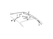
2007 Toyota Camry Antenna
Part Number: 86300-06071$342.08 MSRP: $501.32You Save: $159.24 (32%)Ships in 1-3 Business DaysProduct Specifications- Other Name: Antenna Assembly, Amplifier; Antenna Amplifier; Amplifier
- Replaces: 86300-06070, 86300-33310, 86300-33311
- Part Name Code: 86300B
- Item Weight: 0.90 Pounds
- Item Dimensions: 12.0 x 3.8 x 1.8 inches
- Condition: New
- Fitment Type: Direct Replacement
- SKU: 86300-06071
- Warranty: This genuine part is guaranteed by Toyota's factory warranty.
2007 Toyota Camry Antenna
Part Number: 86300-06080$334.80 MSRP: $478.02You Save: $143.22 (30%)Ships in 1-3 Business DaysProduct Specifications- Other Name: Antenna Assembly, Amplifier; Antenna Amplifier; Amplifier
- Part Name Code: 86300B
- Item Weight: 0.90 Pounds
- Item Dimensions: 12.2 x 4.0 x 1.8 inches
- Condition: New
- Fitment Type: Direct Replacement
- SKU: 86300-06080
- Warranty: This genuine part is guaranteed by Toyota's factory warranty.
2007 Toyota Camry Antenna
Looking for affordable OEM 2007 Toyota Camry Antenna? Explore our comprehensive catalogue of genuine 2007 Toyota Camry Antenna. All our parts are covered by the manufacturer's warranty. Plus, our straightforward return policy and speedy delivery service ensure an unparalleled shopping experience. We look forward to your visit!
2007 Toyota Camry Antenna Parts Q&A
- Q: How to remove and install the navigation antenna on 2007 Toyota Camry?A: The first step for navigation antenna removal requires aligning the front wheels straight ahead while waiting for 90 seconds with the negative battery cable disconnected to avoid triggering the Air Bags. The first step involves taking away the lower No. 3 steering wheel cover, lower No. 2 steering wheel cover and steering pad before working on the steering wheel assembly. Next, remove the front door scuff plate LH, cowl side trim sub-assembly LH, lower instrument panel finish panel LH (for TMC Made and TMMK Made), steering column cover (for TMC Made and TMMK Made), turn signal switch assembly with spiral cable sub-assembly, No. 1 instrument panel subassembly, lower instrument panel finish panel (with and without Smart Key System), instrument cluster finish panel, combination meter assembly (for TMC Made and TMMK Made), front door scuff plate RH, cowl side trim sub-assembly RH, instrument panel No. 2 under cover sub-assembly, lower instrument panel subassembly (for TMC Made and TMMK Made), shift lever knob sub-assembly (for both Automatic and Manual Transaxle), No. 1 and No. 2 instrument cluster finish panel garnish, floor shift position indicator housing sub-assembly (for Automatic Transaxle), upper console panel (for Manual Transaxle), upper console rear panel subassembly (for both Automatic and Manual Transaxle), upper console panel sub-assembly (for TMC Made and TMMK Made), instrument panel No. 2 register assembly, navigation receiver with heater control panel assembly, console box pocket, console box carpet, console box assembly (for TMC Made and TMMK Made), No. 2 and No. 1 console box insert front (for both TMC Made and TMMK Made), front pillar garnish LH, instrument panel No. 1 register assembly, instrument panel No. 1 speaker panel sub-assembly, front No. 2 speaker assembly (for LH Side), front pillar garnish RH, instrument panel No. 3 register assembly, instrument panel No. 2 speaker panel sub-assembly, and front No. 2 speaker assembly (for RH Side). The staff should handle both sides through identical processes. Both TMC Made and TMMK Made require removal of the No. 1 defroster nozzle garnish and instrument panel safety pad assembly along with side No. 1 and No. 2 defroster nozzle duct and defroster nozzle assembly. Workers should remove the No. 1, No. 2, and No. 3 heater to register duct (for both TMC Made and TMMK Made) before completing the procedure by taking out the navigation antenna assembly through clamp and screw removal. For installation, begin by installing the navigation antenna assembly with the 2 screws and engaging the 3 clamps, followed by the No. 2, No. 3, and No. 1 heater to register duct (for both TMC Made and TMMK Made), defroster nozzle assembly (for both TMC Made and TMMK Made), side No. 2 and No. 1 defroster nozzle duct (for both TMC Made and TMMK Made), instrument panel safety pad assembly (for both TMC Made and TMMK Made), No. 1 defroster nozzle garnish, front No. 2 speaker assembly (for LH and RH Side), instrument panel No. 1 speaker panel sub-assembly, instrument panel No. 1 register assembly, front pillar garnish LH, instrument panel No. 2 speaker panel sub-assembly, instrument panel No. 3 register assembly, front pillar garnish RH, No. 1 and No. 2 console box insert front (for both TMC Made and TMMK Made), console box assembly (for both TMC Made and TMMK Made), console box carpet, console box pocket, navigation receiver with heater control panel assembly, instrument panel No. 2 register assembly, upper console panel sub-assembly (for both TMC Made and TMMK Made), upper console rear panel subassembly (for both Automatic and Manual Transaxle), floor shift position indicator housing sub-assembly (for Automatic Transaxle), upper console panel (for Manual Transaxle), No. 2 and No. 1 instrument cluster finish panel garnish, shift lever knob sub-assembly (for both Automatic and Manual Transaxle), lower instrument panel subassembly (for both TMC Made and TMMK Made), instrument panel No. 2 under cover sub-assembly, cowl side trim sub-assembly RH, front door scuff plate RH, combination meter assembly (for both TMC Made and TMMK Made), instrument cluster finish panel, lower instrument panel finish panel (with and without Smart Key System), No. 1 instrument panel subassembly, turn signal switch assembly with spiral cable sub-assembly, and adjust the spiral cable sub-assembly. As the last steps install the steering column cover (both TMC Made and TMMK Made) then position the lower instrument panel finish panel LH (for TMC Made and TMMK Made) followed by cowl side trim sub-assembly LH and front door scuff plate LH and steering wheel assembly with steering pad and lower No. 3 steering wheel cover and lower No. 2 steering wheel cover. Afterward reconnect the cable to the negative battery terminal and examine the steering pad and SRS warning light.
Related 2007 Toyota Camry Parts
 2007 Toyota Camry Ignition Switch
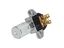 2007 Toyota Camry Dimmer Switch
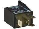 2007 Toyota Camry Headlight Relay
 2007 Toyota Camry Horn
 2007 Toyota Camry Relay
 2007 Toyota Camry Door Jamb Switch
 2007 Toyota Camry Antenna Cable
 2007 Toyota Camry Hazard Warning Switch
 2007 Toyota Camry Ignition Lock Assembly
 2007 Toyota Camry Ignition Lock Cylinder
 2007 Toyota Camry Transmitter
 2007 Toyota Camry Turn Signal Flasher