×
ToyotaParts- Hello
- Login or Register
- Quick Links
- Live Chat
- Track Order
- Parts Availability
- RMA
- Help Center
- Contact Us
- Shop for
- Toyota Parts
- Scion Parts
My Garage
My Account
Cart
OEM 2007 Scion tC Knock Sensor
Engine Knock Sensor- Select Vehicle by Model
- Select Vehicle by VIN
Select Vehicle by Model
orMake
Model
Year
Select Vehicle by VIN
For the most accurate results, select vehicle by your VIN (Vehicle Identification Number).
1 Knock Sensor found


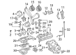
2007 Scion tC Knock Sensor
Part Number: 89615-06010$138.05 MSRP: $195.42You Save: $57.37 (30%)Ships in 1-3 Business DaysProduct Specifications- Other Name: Sensor, Knock Control; Ignition Knock (Detonation) Sensor
- Replaces: 89615-BZ030, 89615-20090, 89615-BZ040
- Part Name Code: 89615
- Item Weight: 0.40 Pounds
- Item Dimensions: 4.1 x 1.9 x 1.4 inches
- Condition: New
- Fitment Type: Direct Replacement
- SKU: 89615-06010
- Warranty: This genuine part is guaranteed by Toyota's factory warranty.
2007 Scion tC Knock Sensor
Looking for affordable OEM 2007 Scion tC Knock Sensor? Explore our comprehensive catalogue of genuine 2007 Scion tC Knock Sensor. All our parts are covered by the manufacturer's warranty. Plus, our straightforward return policy and speedy delivery service ensure an unparalleled shopping experience. We look forward to your visit!
2007 Scion tC Knock Sensor Parts Q&A
- Q: How to service the knock sensor on 2007 Scion tC?A: In order to maintain the the knock sensor, release the fuel system pressure and empty the coolant. Disassemble the negative battery terminal, and then take off different parts such as the wiper arms, cowl top panel and intake manifold. Install knock sensor, re-connect hoses, and make sure that all connections are properly torqued. Last, test for leaks and re-attach other components.
Related 2007 Scion tC Parts
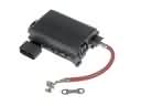 2007 Scion tC Fuse Box
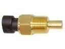 2007 Scion tC Coolant Temperature Sensor
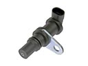 2007 Scion tC Crankshaft Position Sensor
 2007 Scion tC Headlight Relay
 2007 Scion tC Ignition Coil
 2007 Scion tC Mass Air Flow Sensor
 2007 Scion tC Daytime Running Light Relay
 2007 Scion tC Engine Control Module
 2007 Scion tC Relay
 2007 Scion tC Relay Block
 2007 Scion tC Spark Plug
 2007 Scion tC Turn Signal Flasher