×
ToyotaParts- Hello
- Login or Register
- Quick Links
- Live Chat
- Track Order
- Parts Availability
- RMA
- Help Center
- Contact Us
- Shop for
- Toyota Parts
- Scion Parts
My Garage
My Account
Cart
OEM 2006 Toyota Tacoma Antenna Cable
Radio Antenna Cable- Select Vehicle by Model
- Select Vehicle by VIN
Select Vehicle by Model
orMake
Model
Year
Select Vehicle by VIN
For the most accurate results, select vehicle by your VIN (Vehicle Identification Number).
1 Antenna Cable found


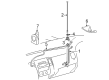
2006 Toyota Tacoma Antenna Cable
Part Number: 86101-04010$104.51 MSRP: $146.69You Save: $42.18 (29%)Ships in 1-3 Business DaysProduct Specifications- Other Name: Cord Sub-Assembly, Antenna
- Part Name Code: 86101
- Item Weight: 0.60 Pounds
- Item Dimensions: 15.4 x 6.0 x 2.1 inches
- Condition: New
- Fitment Type: Direct Replacement
- SKU: 86101-04010
- Warranty: This genuine part is guaranteed by Toyota's factory warranty.
2006 Toyota Tacoma Antenna Cable
Looking for affordable OEM 2006 Toyota Tacoma Antenna Cable? Explore our comprehensive catalogue of genuine 2006 Toyota Tacoma Antenna Cable. All our parts are covered by the manufacturer's warranty. Plus, our straightforward return policy and speedy delivery service ensure an unparalleled shopping experience. We look forward to your visit!
2006 Toyota Tacoma Antenna Cable Parts Q&A
- Q: How to service and repair the antenna cable on 2006 Toyota Tacoma?A: Begin the antenna cable repair process by taking it off the negative battery terminal. Take out the front footrest plus front door scuff plates from both sides and cowl side trim panels while splitting the front door opening Weather Strips. Service starts by taking off the LH and RH front pillar garnishes and the under tray from instrument panel when parking brake uses pedals and placing aside the instrument panel's hole cover for lever brakes. Take out the rear box and instrument panel cup holder tray (for automatic transmission users of separate seats) and remove the front console boxes from the separate and bench seats on automatic and manual transmissions. Take the air conditioner controls out with the radio receiver unit and break apart the hood lock control lever. Proceed by taking the No. 1 lower instrument panel finish panel, instrument cluster finish panel sub-assembly, combination meter assembly, instrument cluster center finish panel sub-assembly, glove compartment door assembly, instrument panel lower finish panel sub-assembly (RH), lower instrument panel (LH), and instrument lower cover subassembly apart. Take out the instrument side panel from the right side and disconnect the passenger Air Bag connector before taking out both the instrument panel passenger Air Bag assembly and instrument panel sub-assembly. After you finish all steps unclick the four claws to take out the radio antenna cord sub-assembly. Begin installation by fitting the antenna cord sub-assembly using all 4 claws before putting on the instrument panel and its connected passenger Air Bag while reinspecting the passenger Air Bag connector. Add these components one after another in the correct sequence: instrument side panel (RH), instrument lower cover subassembly, lower instrument panel (LH), instrument panel lower finish panel sub-assembly (RH), glove compartment door assembly, center instrument cluster finish panel sub-assembly, combination meter assembly, instrument cluster finish panel sub-assembly, and No. 1 lower instrument panel finish panel. Add the hood lock control piece and the radio receiver trim to your installation with the air conditioning control device and front console pieces (one set for manual transmission plus bench seat and another set for the automatic transmission). Put the automatic transmission instrument panel cup holder tray along with the rear console box assembly for separate seat types and console upper rear panels for all transmission and seat types. Position first the instrument panel hole cover (for lever brake) and instrument panel under tray (for pedal brake). Add next the front pillar garnishes on both sides with their Weather Strips. Install each cowl side trim board and front door scuff plates including the left and right ones. Place lastly the front floor footrest. Connect the battery cable to its negative terminal and use a torque of 3.9 N.m to fasten it.
Related 2006 Toyota Tacoma Parts
 2006 Toyota Tacoma Antenna
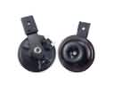 2006 Toyota Tacoma Horn
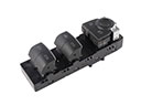 2006 Toyota Tacoma Power Window Switch
 2006 Toyota Tacoma Seat Belt
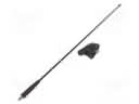
 2006 Toyota Tacoma Antenna Mast
 2006 Toyota Tacoma ABS Control Module
 2006 Toyota Tacoma ABS Relay
 2006 Toyota Tacoma Car Key
 2006 Toyota Tacoma Daytime Running Light Relay
 2006 Toyota Tacoma Mirror Switch
 2006 Toyota Tacoma Relay
 2006 Toyota Tacoma Relay Block