×
ToyotaParts- Hello
- Login or Register
- Quick Links
- Live Chat
- Track Order
- Parts Availability
- RMA
- Help Center
- Contact Us
- Shop for
- Toyota Parts
- Scion Parts
My Garage
My Account
Cart
OEM 2006 Toyota Solara Fuel Tank
Gas Tank- Select Vehicle by Model
- Select Vehicle by VIN
Select Vehicle by Model
orMake
Model
Year
Select Vehicle by VIN
For the most accurate results, select vehicle by your VIN (Vehicle Identification Number).
1 Fuel Tank found

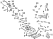 Product Specifications
- Other Name: Tank Sub-Assembly, Fuel; Fuel Tank
- Replaces: 77001-06111, 77001-33192
- Part Name Code: 77100
- Item Weight: 36.90 Pounds
- Item Dimensions: 15.3 x 10.5 x 49.7 inches
- Condition: New
- Fitment Type: Direct Replacement
- SKU: 77001-06112
- Warranty: This genuine part is guaranteed by Toyota's factory warranty.
2006 Toyota Solara Fuel Tank
Looking for affordable OEM 2006 Toyota Solara Fuel Tank? Explore our comprehensive catalogue of genuine 2006 Toyota Solara Fuel Tank. All our parts are covered by the manufacturer's warranty. Plus, our straightforward return policy and speedy delivery service ensure an unparalleled shopping experience. We look forward to your visit!
2006 Toyota Solara Fuel Tank Parts Q&A
- Q: How to service and repair the fuel tank on 2006 Toyota Solara?A: In order to service the fuel tank, bleed the fuel system, remove the rear seat cushion and the fuel pump assembly. empty fuel, cable disconnection, tank removal. Change new cushions, re-connect components, and fix everything. Lastly, make sure that there are no leaks and replace the rear seat and floor panel brace.
Related 2006 Toyota Solara Parts
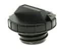 2006 Toyota Solara Gas Cap
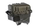 2006 Toyota Solara Air Filter Box
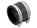 2006 Toyota Solara Air Intake Coupling
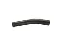 2006 Toyota Solara Fuel Filler Hose
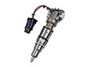 2006 Toyota Solara Fuel Injector
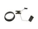 2006 Toyota Solara Fuel Level Sensor
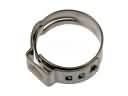 2006 Toyota Solara Fuel Line Clamps
 2006 Toyota Solara Fuel Pressure Regulator
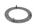 2006 Toyota Solara Fuel Pump Gasket
 2006 Toyota Solara Fuel Pump Seal
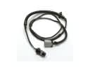 2006 Toyota Solara Fuel Pump Wiring Harness
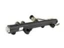 2006 Toyota Solara Fuel Rail