×
ToyotaParts- Hello
- Login or Register
- Quick Links
- Live Chat
- Track Order
- Parts Availability
- RMA
- Help Center
- Contact Us
- Shop for
- Toyota Parts
- Scion Parts
My Garage
My Account
Cart
OEM 2006 Toyota Matrix Starter Motor
Starter Ignition- Select Vehicle by Model
- Select Vehicle by VIN
Select Vehicle by Model
orMake
Model
Year
Select Vehicle by VIN
For the most accurate results, select vehicle by your VIN (Vehicle Identification Number).
1 Starter Motor found


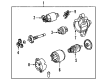
2006 Toyota Matrix Starter
Part Number: 28100-0D080-84$95.68 MSRP: $132.80You Save: $37.12 (28%)Ships in 1-3 Business DaysProduct Specifications- Other Name: Reman Starter 1Zz-Fe; Starter Motor
- Item Weight: 10.40 Pounds
- Item Dimensions: 9.1 x 7.1 x 5.3 inches
- Condition: New
- SKU: 28100-0D080-84
- Warranty: This genuine part is guaranteed by Toyota's factory warranty.
2006 Toyota Matrix Starter Motor
Looking for affordable OEM 2006 Toyota Matrix Starter Motor? Explore our comprehensive catalogue of genuine 2006 Toyota Matrix Starter Motor. All our parts are covered by the manufacturer's warranty. Plus, our straightforward return policy and speedy delivery service ensure an unparalleled shopping experience. We look forward to your visit!
2006 Toyota Matrix Starter Motor Parts Q&A
- Q: How to overhaul the starter motor on 2006 Toyota Matrix?A: The overhauling process begins with disconnection of the lead wire followed by screw removal to release the magnet switch body from the motor. The continued operation involves extracting both the switch and return spring alongside plunger from the drive housing. Start by extracting the through bolts and then pull out the yoke with its associated starter commutator end frame before splitting them apart. To access the starter commutator end frame cover you must first separate the starter armature plate from the starter yoke after which you can use a screwdriver to carry out the removal process. A snap ring plier removes the snap ring while the washer and starter armature need to be taken out from the end frame. Extract first the three planetary gears from the starter center bearing clutch and next extract the starter center bearing clutch together with the starter drive lever set pin from the starter drive housing. The clutch requires removal of its starter drive lever set pin. Testing the magnet switch's body should confirm its operational status and resistance levels between terminals 50 and C at 1 Ohm or less and 50 to switch body at 2.0 Ohm or below. Replace the switch if standards are not met. Measure starter armature assembly resistance in three ways: the commutator segments must be under 1 Ohm while maintaining 10 kOhms or higher between the commutator and armature coil core; the components need replacement if these standards are not achieved. Use vernier calipers to measure the commutator depth between 3.1 mm and 3.8 mm after sanding off any burned areas with 400-grit sandpaper. Replace the component if the measurement exceeds the maximum value. The starter commutator end frame assembly must be checked for brush length which should be 9.0 mm but never less than 4.0 mm and the brush resistance should exceed 10 kOhms; any necessary repairs or replacements must be performed. Check the starter center bearing clutch sub-assembly for operation quality by observing the clutch pinion gear which should rotate freely clockwise and lock counterclockwise; replace if the parts exhibit wear or damage. The starter drive lever set pin must go into the starter center bearing clutch before installing the clutch into the starter drive housing. You should apply grease onto planetary gears before placing them inside the starter center bearing clutch. When assembling the starter armature piece apply grease to the washer and shaft then mount them into the starter commutator end frame before attaching a new snap ring and checking that the length stays below 5.0 mm. Install the starter commutator end frame cover afterward to put the starter armature plate together with the starter commutator end frame inside the starter yoke. To complete installation, physicians should first align the starter yoke properly with the starter drive housing then tighten the through bolts to 6.0 N.m. Afterward they must install the magnet switch body by applying grease to the plunger and hook before hanging the plunger hook onto the starter drive lever set pin. The plunger requires installation with the return spring before securing the magnet switch with screws to 7.5 N.m and connecting the lead wire to terminal C with a nut tightened to 10 N.m.
Related 2006 Toyota Matrix Parts
 2006 Toyota Matrix Starter Solenoid
 2006 Toyota Matrix Alternator Bearing
 2006 Toyota Matrix Alternator Bracket
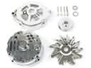 2006 Toyota Matrix Alternator Case Kit
 2006 Toyota Matrix Alternator Pulley
 2006 Toyota Matrix Armature
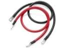 2006 Toyota Matrix Battery Cable
 2006 Toyota Matrix Battery Terminal
 2006 Toyota Matrix Battery Tray
 2006 Toyota Matrix Car Batteries
 2006 Toyota Matrix Starter Drive Gear
 2006 Toyota Matrix Voltage Regulator