×
ToyotaParts- Hello
- Login or Register
- Quick Links
- Live Chat
- Track Order
- Parts Availability
- RMA
- Help Center
- Contact Us
- Shop for
- Toyota Parts
- Scion Parts
My Garage
My Account
Cart
OEM 2006 Toyota Matrix Parking Brake Shoe
Emergency Parking Brake Shoe- Select Vehicle by Model
- Select Vehicle by VIN
Select Vehicle by Model
orMake
Model
Year
Select Vehicle by VIN
For the most accurate results, select vehicle by your VIN (Vehicle Identification Number).
3 Parking Brake Shoes found


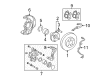
2006 Toyota Matrix Brake Shoes, Rear
Part Number: 04495-01040$51.73 MSRP: $72.01You Save: $20.28 (29%)Ships in 1-3 Business DaysProduct Specifications- Other Name: Shoe Kit, Brake, Rear; Drum Brake Shoe, Rear; Parking Brake Shoe; Shoe Kit, Rear Brake
- Manufacturer Note: MARK NAC LN521
- Position: Rear
- Part Name Code: 04495
- Item Weight: 4.10 Pounds
- Item Dimensions: 10.4 x 8.1 x 3.6 inches
- Condition: New
- Fitment Type: Direct Replacement
- SKU: 04495-01040
- Warranty: This genuine part is guaranteed by Toyota's factory warranty.


2006 Toyota Matrix Parking Brake Shoes, Rear
Part Number: 46540-20080$33.93 MSRP: $47.22You Save: $13.29 (29%)Ships in 1-3 Business DaysProduct Specifications- Other Name: Shoe Assembly, Parking Brake; Parking Brake Shoe, Rear; Shoes; Parking Brake Shoe Assembly, Passenger Side Or Center & Driver Side.
- Manufacturer Note: SPECIAL EDITION(USA)
- Position: Rear
- Replaces: 46540-32020
- Item Weight: 1.40 Pounds
- Item Dimensions: 12.6 x 3.5 x 7.3 inches
- Condition: New
- Fitment Type: Direct Replacement
- SKU: 46540-20080
- Warranty: This genuine part is guaranteed by Toyota's factory warranty.

2006 Toyota Matrix Brake Shoes, Rear
Part Number: 04495-63011$57.83 MSRP: $80.49You Save: $22.66 (29%)Ships in 1-3 Business DaysProduct Specifications- Other Name: Shoe Kit, Brake, Rear; Drum Brake Shoe, Rear; Parking Brake Shoe; Shoe Kit, Rear Brake
- Manufacturer Note: MARK AKB LA509A
- Position: Rear
- Part Name Code: 04495
- Item Weight: 5.30 Pounds
- Item Dimensions: 18.9 x 13.7 x 3.1 inches
- Condition: New
- Fitment Type: Direct Replacement
- SKU: 04495-63011
- Warranty: This genuine part is guaranteed by Toyota's factory warranty.
2006 Toyota Matrix Parking Brake Shoe
Looking for affordable OEM 2006 Toyota Matrix Parking Brake Shoe? Explore our comprehensive catalogue of genuine 2006 Toyota Matrix Parking Brake Shoe. All our parts are covered by the manufacturer's warranty. Plus, our straightforward return policy and speedy delivery service ensure an unparalleled shopping experience. We look forward to your visit!
2006 Toyota Matrix Parking Brake Shoe Parts Q&A
- Q: How to overhaul the parking brake shoe on the RH side on 2006 Toyota Matrix?A: Overhauling the parking brake shoe on the RH side requires following the same step-by-step process as on the LH side by starting with rear wheel removal. The rear brake caliper assembly LH needs to be disconnected before removing the rear disc brake and the wheel turns freely through adjusting the shoe when the disc is hard to remove. A brake drum gauge should be used to check the inside diameter of the brake disc where measurements need to fall between 173 mm (6.81 inch) and 174 mm (6.85 inch). You can remove the parking brake shoe strut LH by first unscrewing its two upper side tension springs with needle-nose pliers before extracting the strut from its position. The procedure to remove the parking brake shoe adjusting screw set begins with removing both the anchor side tension spring and screw set components. Special Service Tool 09718-00010 enables removal of the parking brake shoe assembly LH No.1 by first removing its hold-down compression spring and hold-down spring pin and lastly the assembly itself. The procedure must be repeated for the parking brake shoe assembly LH No.2 by detaching it from the parking brake shoe lever LH. A ruler should be used to verify that shoe linings reach 3.5 mm (0.138 inch) thickness and have no less than 1.0 mm (0.039 inch) thickness. Brush chalk on the inner disc surface to check contact quality with the lining and adjust it with a brake shoe grinder or exchange the assembly. Remove the parking brake shoe lever LH following disconnecting the parking brake cable assembly No.3. High-temperature grease needs application on the backing plate shoe attached surface before reinstalling both the parking brake lever LH and its cable assembly connection. High-temperature grease should be applied to the parking brake shoe assembly LH No.2 before installation with Special Service Tool: 09718-00010 and the use of hold-down compression spring and hold-down spring pin. The installation process for parking brake shoe assembly LH No.1 should be repeated once more. Install the parking brake shoe adjusting screw set along with its tension spring only after applying high-temperature grease to both the adjusting bolt and support piece. The left-hand parking brake shoe strut requires high-temperature grease on contact points before its installation with upper side tension springs secured into their respective grooves. Confirm all components are correctly located and verify that oil and grease remains off the shoe lining friction surface and disc. Adhere the rear disc in place and modify the parking brake shoe clearance through the temporary attachment of hub nuts and hole plug extraction followed by shoe expansion until the disc becomes locked. After the disc moves freely the adjuster should be contracted to achieve 8 notches before reinstalling the hole plug and rear disc brake caliper assembly LH. Reinstall the rear wheel with 103 Nm (1,050 kgf-cm, 76 ft. lbs.) torque. The hole plug must be securely installed after eliminating brake drag during installation of the rear disc brake caliper assembly LH and the rear wheel application using 103 Nm (1,050 kgf-cm, 76 ft. lbs.) torque. Check and readjust the parking brake lever travel during the last steps of the process.
Related 2006 Toyota Matrix Parts
 2006 Toyota Matrix Brake Caliper
 2006 Toyota Matrix Wheel Bearing
 2006 Toyota Matrix Brake Caliper Bracket
 2006 Toyota Matrix Brake Caliper Piston
 2006 Toyota Matrix Brake Disc
 2006 Toyota Matrix Brake Drum
 2006 Toyota Matrix Brake Line
 2006 Toyota Matrix Brake Pad Set
 2006 Toyota Matrix Brake Proportioning Valve
 2006 Toyota Matrix Hydraulic Hose
 2006 Toyota Matrix Spindle Nut
 2006 Toyota Matrix Wheel Hub