×
ToyotaParts- Hello
- Login or Register
- Quick Links
- Live Chat
- Track Order
- Parts Availability
- RMA
- Help Center
- Contact Us
- Shop for
- Toyota Parts
- Scion Parts
My Garage
My Account
Cart
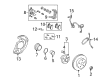
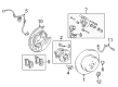
OEM 2006 Toyota Highlander Brake Caliper
Caliper- Select Vehicle by Model
- Select Vehicle by VIN
Select Vehicle by Model
orMake
Model
Year
Select Vehicle by VIN
For the most accurate results, select vehicle by your VIN (Vehicle Identification Number).
8 Brake Calipers found


2006 Toyota Highlander Caliper, Driver Side
Part Number: 47750-48060$227.16 MSRP: $324.34You Save: $97.18 (30%)Ships in 1-3 Business DaysProduct Specifications- Other Name: Cylinder Assembly, Disc; Disc Brake Caliper, Front Left; Cylinder Assembly, Disc Brake, Driver Side; Brake Caliper
- Position: Driver Side
- Part Name Code: 47750
- Item Weight: 12.00 Pounds
- Item Dimensions: 10.3 x 7.8 x 5.4 inches
- Condition: New
- Fitment Type: Direct Replacement
- SKU: 47750-48060
- Warranty: This genuine part is guaranteed by Toyota's factory warranty.


2006 Toyota Highlander Caliper, Passenger Side
Part Number: 47730-48060$227.16 MSRP: $324.34You Save: $97.18 (30%)Ships in 1-3 Business DaysProduct Specifications- Other Name: Cylinder Assembly, Disc; Disc Brake Caliper, Front Right; Cylinder Assembly, Front Disc Brake, Passenger Side; Brake Caliper
- Position: Passenger Side
- Part Name Code: 47730
- Item Weight: 11.40 Pounds
- Item Dimensions: 10.3 x 7.8 x 5.6 inches
- Condition: New
- Fitment Type: Direct Replacement
- SKU: 47730-48060
- Warranty: This genuine part is guaranteed by Toyota's factory warranty.


2006 Toyota Highlander Caliper, Driver Side
Part Number: 47750-48130$282.27 MSRP: $403.01You Save: $120.74 (30%)Ships in 1-3 Business DaysProduct Specifications- Other Name: Cylinder Assembly, Disc; Disc Brake Caliper, Front Left; Cylinder Assembly, Disc Brake, Driver Side; Brake Caliper
- Position: Driver Side
- Part Name Code: 47750
- Item Weight: 14.50 Pounds
- Item Dimensions: 10.3 x 7.5 x 5.4 inches
- Condition: New
- Fitment Type: Direct Replacement
- SKU: 47750-48130
- Warranty: This genuine part is guaranteed by Toyota's factory warranty.

2006 Toyota Highlander Cylinder Assembly, Disc Brake, Driver Side
Part Number: 47750-48140$142.63 MSRP: $201.92You Save: $59.29 (30%)Ships in 1-3 Business DaysProduct Specifications- Other Name: Cylinder Assembly, Disc; Brake Caliper
- Position: Driver Side
- Part Name Code: 47750
- Item Weight: 4.00 Pounds
- Item Dimensions: 10.4 x 8.0 x 5.6 inches
- Condition: New
- Fitment Type: Direct Replacement
- SKU: 47750-48140
- Warranty: This genuine part is guaranteed by Toyota's factory warranty.
2006 Toyota Highlander Cylinder Assembly, Front Disc Brake, Passenger Side
Part Number: 47730-48140$172.71 MSRP: $244.50You Save: $71.79 (30%)Ships in 1-3 Business DaysProduct Specifications- Other Name: Cylinder Assembly, Disc; Brake Caliper
- Position: Passenger Side
- Part Name Code: 47730
- Item Weight: 12.30 Pounds
- Item Dimensions: 9.9 x 8.1 x 5.5 inches
- Condition: New
- Fitment Type: Direct Replacement
- SKU: 47730-48140
- Warranty: This genuine part is guaranteed by Toyota's factory warranty.

2006 Toyota Highlander Cylinder Assembly, Disc Brake, Rear Driver Side
Part Number: 47850-48050$129.94 MSRP: $183.95You Save: $54.01 (30%)Ships in 1-3 Business DaysProduct Specifications- Other Name: Cylinder Assembly, Rear Disc Brake; Brake Caliper
- Position: Rear Driver Side
- Part Name Code: 47750A
- Item Weight: 6.80 Pounds
- Item Dimensions: 10.4 x 10.8 x 10.0 inches
- Condition: New
- Fitment Type: Direct Replacement
- SKU: 47850-48050
- Warranty: This genuine part is guaranteed by Toyota's factory warranty.
2006 Toyota Highlander Caliper, Passenger Side
Part Number: 47830-48050$132.65 MSRP: $187.78You Save: $55.13 (30%)Ships in 1-3 Business DaysProduct Specifications- Other Name: Cylinder Assembly, Rear Disc Brake; Disc Brake Caliper, Rear Right; Cylinder Assembly, Rear Disc Brake, Passenger Side; Brake Caliper
- Position: Passenger Side
- Part Name Code: 47730B
- Item Weight: 6.20 Pounds
- Condition: New
- Fitment Type: Direct Replacement
- SKU: 47830-48050
- Warranty: This genuine part is guaranteed by Toyota's factory warranty.
2006 Toyota Highlander Caliper, Passenger Side
Part Number: 47730-48130$282.27 MSRP: $403.01You Save: $120.74 (30%)Ships in 1-3 Business DaysProduct Specifications- Other Name: Cylinder Assembly, Disc; Disc Brake Caliper, Front Right; Cylinder Assembly, Front Disc Brake, Passenger Side; Brake Caliper
- Position: Passenger Side
- Part Name Code: 47730
- Item Weight: 14.30 Pounds
- Item Dimensions: 9.9 x 7.8 x 5.4 inches
- Condition: New
- Fitment Type: Direct Replacement
- SKU: 47730-48130
- Warranty: This genuine part is guaranteed by Toyota's factory warranty.
2006 Toyota Highlander Brake Caliper
Looking for affordable OEM 2006 Toyota Highlander Brake Caliper? Explore our comprehensive catalogue of genuine 2006 Toyota Highlander Brake Caliper. All our parts are covered by the manufacturer's warranty. Plus, our straightforward return policy and speedy delivery service ensure an unparalleled shopping experience. We look forward to your visit!
2006 Toyota Highlander Brake Caliper Parts Q&A
- Q: How to service and repair the front brake caliper on 2006 Toyota Highlander?A: Service and repair Front brake calipers begin with removing the 2 brake pads with anti-squeal shim from cylinder mounting LH followed by extracting 2 anti-squeal shims from each pad and the pad wear indicator from the inner pad using a screwdriver. First separate front disc brake pad support plates (No. 1 and No. 2) from the front disc brake cylinder mounting LH. Then remove the 2 front disc brake cylinder slide pins along with the front disc brake cylinder slide bush attached to the lower slide pin. During this process maintain slide pin No. 2 from any damage. Use a screwdriver to carefully remove the front disc brake cylinder boot from its location by keeping the screwdriver away from the inner cylinder and groove while also removing the 2 bolts which fasten the front disc brake cylinder mounting LH. The extraction process for the front brake piston requires a shop rug between brake cylinder section and the piston while using compressed air but no fingers must extend in front of the piston and ensure no brake fluid droplets form. Operation begins with removing the piston seal through the use of a screwdriver as well as the bleeder plug cap and bleeder plug from the disc brake cylinder sub-assembly. Afterward, measure and mark the front disc and axle hub before proceeding to remove the front disc. The brake cylinder bore and piston should be checked for rust and scoring while pad lining thickness measurements should be taken (must be at least 1.0 mm but standard at 12.7 mm) alongside an evaluation of front disc brake pad support plates for sufficient rebound and cleanliness. Reassemble the front disc component after proper alignment of matchmarks while tightening the hub nuts to 103 Nm temporarily before measuring disc runout at 10 mm from the edge for a maximum variance of 0.05 mm. The inspection process for bearing play and axle hub runout requires adjustments or grinding of the disc when necessary. You must first apply lithium soap base glycol grease to a brand new piston seal then proceed to install it in the disc brake cylinder sub-assembly after tightening the front disc brake bleeder plug temporarily and installing the bleeder plug cap. Apply grease to the front disc brake piston as well as the new cylinder boot before assembly and avoid pushing on the piston during installation. Start by greasing a new cylinder boot then attach it properly before installing a new set ring at the end. Afterward secure the front disc brake cylinder mounting LH with 2 bolts that require 107 Nm torque. Apply grease to the sealing surfaces of two new front disc brake bush dust boots before installation and that follows installation of a new front disc brake cylinder slide bush onto slide pin No. 2. Introduce an appropriate grease to the sliding sections and the seal surfaces of the two slide pins before you install them. Return the front disc brake pad support plates numbered No. 1 and No. 2 to the cylinder mounting LH. Install the disc brake grease on anti-squeal shims and put them into position on pads while disc brake pad replacement must occur with new brake pads and pad wear indicator installation on inner pad surfaces. Install the 2 brake pads with anti-squeal shim to the disc brake cylinder mounting LH after checking for absence of oil and grease on friction surfaces.
Related 2006 Toyota Highlander Parts
 2006 Toyota Highlander Wheel Bearing
 2006 Toyota Highlander Speed Sensor
 2006 Toyota Highlander ABS Pump And Motor Assembly
 2006 Toyota Highlander Backing Plate
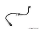 2006 Toyota Highlander Brake Booster Vacuum Hose
 2006 Toyota Highlander Brake Pad Set
 2006 Toyota Highlander Brake Shoe Set
 2006 Toyota Highlander Parking Brake Shoe
 2006 Toyota Highlander Spindle Nut
 2006 Toyota Highlander Wheel Cylinder
 2006 Toyota Highlander Wheel Cylinder Repair Kit
 2006 Toyota Highlander Wheel Hub