×
ToyotaParts- Hello
- Login or Register
- Quick Links
- Live Chat
- Track Order
- Parts Availability
- RMA
- Help Center
- Contact Us
- Shop for
- Toyota Parts
- Scion Parts
My Garage
My Account
Cart
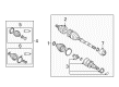
OEM 2006 Toyota Corolla Axle Shaft
Car Axle Shaft- Select Vehicle by Model
- Select Vehicle by VIN
Select Vehicle by Model
orMake
Model
Year
Select Vehicle by VIN
For the most accurate results, select vehicle by your VIN (Vehicle Identification Number).
11 Axle Shafts found

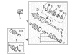
2006 Toyota Corolla Axle Assembly, Driver Side
Part Number: 43420-02360$387.70 MSRP: $568.18You Save: $180.48 (32%)Ships in 1-3 Business DaysProduct Specifications- Other Name: Shaft Assembly, Front Drive; CV Axle Assembly, Front Left; GSP Cv Axle; Axle Shaft; Shaft Assembly, Front Drive, Driver Side; CV Axle Assembly
- Position: Driver Side
- Part Name Code: 43420
- Item Weight: 14.60 Pounds
- Item Dimensions: 29.5 x 7.4 x 6.4 inches
- Condition: New
- Fitment Type: Direct Replacement
- SKU: 43420-02360
- Warranty: This genuine part is guaranteed by Toyota's factory warranty.
2006 Toyota Corolla Axle Assembly, Driver Side
Part Number: 43420-02320$404.05 MSRP: $592.14You Save: $188.09 (32%)Ships in 1-3 Business DaysProduct Specifications- Other Name: Shaft Assembly, Front Drive; CV Axle Assembly, Front Left; GSP Cv Axle; Axle Shaft; Shaft Assembly, Front Drive, Driver Side; CV Axle Assembly
- Manufacturer Note: W(ABS)
- Position: Driver Side
- Part Name Code: 43420
- Item Weight: 14.60 Pounds
- Item Dimensions: 30.4 x 7.3 x 6.7 inches
- Condition: New
- Fitment Type: Direct Replacement
- SKU: 43420-02320
- Warranty: This genuine part is guaranteed by Toyota's factory warranty.


 Product Specifications
- Other Name: Shaft Assembly, Front Drive; CV Axle Assembly, Front Right; GSP Cv Axle; Axle Shaft; Axle; Shaft Assembly, Front Drive, Passenger Side; CV Axle Assembly
- Manufacturer Note: W(ABS)
- Position: Passenger Side
- Part Name Code: 43410
- Item Weight: 14.40 Pounds
- Item Dimensions: 29.5 x 7.3 x 6.5 inches
- Condition: New
- Fitment Type: Direct Replacement
- SKU: 43410-02280
- Warranty: This genuine part is guaranteed by Toyota's factory warranty.
- Product Specifications
- Other Name: Shaft Assembly, Front Drive; CV Axle Assembly, Front Right; Axle Shaft
- Position: Front Passenger Side
- Replaces: 43410-02550
- Condition: New
- SKU: 43410-02251
- Warranty: This genuine part is guaranteed by Toyota's factory warranty.
- Product Specifications
- Other Name: Shaft Assembly, Front Drive; CV Axle Assembly, Front Right; GSP Cv Axle; Axle Shaft; Shaft Assembly, Front Drive, Passenger Side; CV Axle Assembly
- Manufacturer Note: W(ABS)
- Position: Passenger Side
- Part Name Code: 43410
- Item Weight: 26.00 Pounds
- Item Dimensions: 44.1 x 5.5 x 5.4 inches
- Condition: New
- Fitment Type: Direct Replacement
- SKU: 43410-02330
- Warranty: This genuine part is guaranteed by Toyota's factory warranty.
- Product Specifications
- Other Name: Shaft Assembly, Front Drive; CV Axle Assembly, Front Left; GSP Cv Axle; Axle Shaft; Shaft Assembly, Front Drive, Driver Side; CV Axle Assembly
- Position: Driver Side
- Part Name Code: 43420
- Item Weight: 16.80 Pounds
- Item Dimensions: 30.1 x 5.2 x 5.3 inches
- Condition: New
- Fitment Type: Direct Replacement
- SKU: 43420-02380
- Warranty: This genuine part is guaranteed by Toyota's factory warranty.
- Product Specifications
- Other Name: Shaft Assembly, Front Drive; CV Axle Assembly, Front Left; GSP Cv Axle; Axle Shaft; Shaft Assembly, Front Drive, Driver Side; CV Axle Assembly
- Position: Driver Side
- Part Name Code: 43420
- Item Weight: 14.80 Pounds
- Item Dimensions: 30.1 x 7.2 x 6.5 inches
- Condition: New
- Fitment Type: Direct Replacement
- SKU: 43420-02580
- Warranty: This genuine part is guaranteed by Toyota's factory warranty.
- Product Specifications
- Other Name: Shaft Assembly, Front Drive; CV Axle Assembly, Front Right; GSP Cv Axle; Axle Shaft; Shaft Assembly, Front Drive, Passenger Side; CV Axle Assembly
- Manufacturer Note: W(ABS)
- Position: Passenger Side
- Part Name Code: 43410
- Item Weight: 14.90 Pounds
- Item Dimensions: 30.1 x 7.5 x 6.4 inches
- Condition: New
- Fitment Type: Direct Replacement
- SKU: 43410-02290
- Warranty: This genuine part is guaranteed by Toyota's factory warranty.
- Product Specifications
- Other Name: Shaft Assembly, Front Drive; CV Axle Assembly, Front Right; GSP Cv Axle; Axle Shaft; Axle; Shaft Assembly, Front Drive, Passenger Side; CV Axle Assembly
- Position: Passenger Side
- Part Name Code: 43410
- Item Weight: 17.70 Pounds
- Item Dimensions: 44.1 x 6.1 x 6.2 inches
- Condition: New
- Fitment Type: Direct Replacement
- SKU: 43410-02350
- Warranty: This genuine part is guaranteed by Toyota's factory warranty.
2006 Toyota Corolla Axle Assembly, Passenger Side
Part Number: 43410-02310$452.63 MSRP: $663.33You Save: $210.70 (32%)Product Specifications- Other Name: Shaft Assembly, Front Drive; CV Axle Assembly, Front Right; GSP Cv Axle; Axle Shaft; Axle; Shaft Assembly, Front Drive, Passenger Side; CV Axle Assembly
- Position: Passenger Side
- Part Name Code: 43410
- Item Weight: 20.20 Pounds
- Item Dimensions: 49.9 x 6.2 x 6.1 inches
- Condition: New
- Fitment Type: Direct Replacement
- SKU: 43410-02310
- Warranty: This genuine part is guaranteed by Toyota's factory warranty.
- Product Specifications
- Other Name: Shaft Assembly, Front Drive; CV Axle Assembly, Front Left; GSP Cv Axle; Axle Shaft; Shaft Assembly, Front Drive, Driver Side; CV Axle Assembly
- Manufacturer Note: W(ABS)
- Position: Driver Side
- Part Name Code: 43420
- Item Weight: 17.60 Pounds
- Item Dimensions: 30.7 x 5.1 x 5.1 inches
- Condition: New
- Fitment Type: Direct Replacement
- SKU: 43420-02340
- Warranty: This genuine part is guaranteed by Toyota's factory warranty.
2006 Toyota Corolla Axle Shaft
Looking for affordable OEM 2006 Toyota Corolla Axle Shaft? Explore our comprehensive catalogue of genuine 2006 Toyota Corolla Axle Shaft. All our parts are covered by the manufacturer's warranty. Plus, our straightforward return policy and speedy delivery service ensure an unparalleled shopping experience. We look forward to your visit!
2006 Toyota Corolla Axle Shaft Parts Q&A
- Q: How to service and repair the axle shaft on 2006 Toyota Corolla?A: Service and repair of the front drive shaft (1ZZ-FE) requires draining manual transaxle oil with 39 Nm torque (400 kgf-cm, 29 ft. lbs.) together with automatic transaxle fluid at 18 Nm (178 kgf-cm, 13 ft. lbs.). You need to first remove the engine under cover LH along with the front wheel then unstake the LH front axle hub nut by using Special Service Tool: 09930-00010 with a hammer and brake application. Selectively unfasten the front stabilizer link assembly LH from shock absorber assembly front LH while also dividing the speed sensor front LH along with its flexible hose from shock absorber and steering knuckle. Detach the tie rod end sub-assembly LH through the use of Special Service Tool: 09628-62011 then disengage the front suspension arm sub-assembly lower No.1 LH from the lower ball joint. A plastic hammer should be used to separate the front drive shaft assembly LH from the front axle assembly LH while taking precautions to safeguard the boot and speed sensor rotor. Disassemble the LH front drive shaft assembly by using Special Service Tool: 09520-01010, 09520-24010 (09520-32040) while holding the hub bearing in place using Specification Service Tool: 09608-16042 (09608-02021, 09608-02041) to protect it from damage. Check the front drive shaft assembly LH for boot damage and play then remove the inboard joint boot clamp No.2 LH as well as the inboard joint boot clamp LH. Clean the old grease from the inboard joint sub-assembly LH while separate the boot from this component and label both the sub-assembly and outboard joint shaft assembly. Disassemble the outboard joint shaft by removing its inner LH shaft snap ring yet keep the roller free from tapping during removal. You must cut the drive shaft damper setting clamp before removing the drive shaft damper. To continue, you need Special Service Tool: 09950-00020 to extract the front drive shaft LH hole snap ring and dust cover LH. Application of Special Service Tool: 09527-10011 allows you to install the new dust cover LH followed by a new LH hole snap ring. Seam the drive shaft damper while positioning the setting clamp at 438 to 442 mm (17.24 to 17.40 inch). Secure the clamp then adjust the angle clearance to 1.5 mm (0.059 inch) or less. Install the inboard joint sub-assembly LH while wrapping the spline with vinyl tape before boot installation, then grease the inboard joint sub-assembly LH with a quantity of 135 to 155 g or 4.8 to 5.5 oz. Secure the inboard joint boot by attaching its clamps while making slightest possible adjustment to the boot clearance. Recheck the front drive shaft assembly LH before installing it while applying ATF for automatic transaxle or manual transaxle gear oil on the spline. Install the drive shaft assembly by correctly positioning the shaft splines while making sure the hole snap ring has its opening side facing in the downward direction. Follow the same step for front drive shaft assembly RH and continue with the installation of front axle assembly LH without damaging the outboard joint boot or speed sensor rotor. The lower front sub-assembly of the suspension arm No.1 LH should receive a torque measurement of 89 Nm (908 kgf-cm, 66 ft. lbs.) before installing the tie rod end sub-assembly LH at 49 Nm (500 kgf-cm, 36 ft. lbs.) with a follow-up installation of a new cotter pin. The speed sensor front LH and its flexible hose need installation using 29 Nm (296 kgf-cm, 21 ft. lbs.) torque followed by a 8.0 Nm (82 kgf-cm, 71 inch lbs.) torque to connect the speed sensor front LH with the steering knuckle. Ensure the sensor remains clean and wire stays untwisted. The assembly of front stabilizer link assembly LH requires a 74 Nm (755 kgf-cm, 55 ft. lbs.) torque along with new hub LH nut installation at 216 Nm (2,200 kgf-cm, 159 ft. lbs.) through staking using a chisel and hammer before installing the front wheel at 103 Nm (1,050 kgf-cm, 76 ft. lbs.). The manual transaxle oil and automatic transaxle fluid need to be added followed by inspections. Front wheel alignment must be examined simultaneously with testing the ABS speed sensor signal.
Related 2006 Toyota Corolla Parts
 2006 Toyota Corolla CV Joint
 2006 Toyota Corolla CV Boot
 2006 Toyota Corolla Shock Absorber
 2006 Toyota Corolla Steering Knuckle
 2006 Toyota Corolla Axle Beam Mount
 2006 Toyota Corolla Bump Stop
 2006 Toyota Corolla Coil Spring Insulator
 2006 Toyota Corolla Shock And Strut Mount
 2006 Toyota Corolla Sway Bar Bracket
 2006 Toyota Corolla Sway Bar Bushing
 2006 Toyota Corolla Sway Bar Kit
 2006 Toyota Corolla Transfer Case Output Shaft Snap Ring