×
ToyotaParts- Hello
- Login or Register
- Quick Links
- Live Chat
- Track Order
- Parts Availability
- RMA
- Help Center
- Contact Us
- Shop for
- Toyota Parts
- Scion Parts
My Garage
My Account
Cart
OEM 2005 Toyota Corolla Axle Shaft
Car Axle Shaft- Select Vehicle by Model
- Select Vehicle by VIN
Select Vehicle by Model
orMake
Model
Year
Select Vehicle by VIN
For the most accurate results, select vehicle by your VIN (Vehicle Identification Number).
11 Axle Shafts found

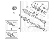
2005 Toyota Corolla Axle Assembly, Driver Side
Part Number: 43420-02360$387.70 MSRP: $568.18You Save: $180.48 (32%)Ships in 1-3 Business DaysProduct Specifications- Other Name: Shaft Assembly, Front Drive; CV Axle Assembly, Front Left; GSP Cv Axle; Axle Shaft; Shaft Assembly, Front Drive, Driver Side; CV Axle Assembly
- Position: Driver Side
- Part Name Code: 43420
- Item Weight: 14.60 Pounds
- Item Dimensions: 29.5 x 7.4 x 6.4 inches
- Condition: New
- Fitment Type: Direct Replacement
- SKU: 43420-02360
- Warranty: This genuine part is guaranteed by Toyota's factory warranty.
2005 Toyota Corolla Axle Assembly, Driver Side
Part Number: 43420-02320$404.05 MSRP: $592.14You Save: $188.09 (32%)Ships in 1-3 Business DaysProduct Specifications- Other Name: Shaft Assembly, Front Drive; CV Axle Assembly, Front Left; GSP Cv Axle; Axle Shaft; Shaft Assembly, Front Drive, Driver Side; CV Axle Assembly
- Manufacturer Note: W(ABS)
- Position: Driver Side
- Part Name Code: 43420
- Item Weight: 14.60 Pounds
- Item Dimensions: 30.4 x 7.3 x 6.7 inches
- Condition: New
- Fitment Type: Direct Replacement
- SKU: 43420-02320
- Warranty: This genuine part is guaranteed by Toyota's factory warranty.


 Product Specifications
- Other Name: Shaft Assembly, Front Drive; CV Axle Assembly, Front Right; GSP Cv Axle; Axle Shaft; Axle; Shaft Assembly, Front Drive, Passenger Side; CV Axle Assembly
- Manufacturer Note: W(ABS)
- Position: Passenger Side
- Part Name Code: 43410
- Item Weight: 14.40 Pounds
- Item Dimensions: 29.5 x 7.3 x 6.5 inches
- Condition: New
- Fitment Type: Direct Replacement
- SKU: 43410-02280
- Warranty: This genuine part is guaranteed by Toyota's factory warranty.
- Product Specifications
- Other Name: Shaft Assembly, Front Drive; CV Axle Assembly, Front Right; Axle Shaft
- Position: Front Passenger Side
- Replaces: 43410-02550
- Condition: New
- SKU: 43410-02251
- Warranty: This genuine part is guaranteed by Toyota's factory warranty.
- Product Specifications
- Other Name: Shaft Assembly, Front Drive; CV Axle Assembly, Front Right; GSP Cv Axle; Axle Shaft; Shaft Assembly, Front Drive, Passenger Side; CV Axle Assembly
- Manufacturer Note: W(ABS)
- Position: Passenger Side
- Part Name Code: 43410
- Item Weight: 26.00 Pounds
- Item Dimensions: 44.1 x 5.5 x 5.4 inches
- Condition: New
- Fitment Type: Direct Replacement
- SKU: 43410-02330
- Warranty: This genuine part is guaranteed by Toyota's factory warranty.
- Product Specifications
- Other Name: Shaft Assembly, Front Drive; CV Axle Assembly, Front Left; GSP Cv Axle; Axle Shaft; Shaft Assembly, Front Drive, Driver Side; CV Axle Assembly
- Position: Driver Side
- Part Name Code: 43420
- Item Weight: 16.80 Pounds
- Item Dimensions: 30.1 x 5.2 x 5.3 inches
- Condition: New
- Fitment Type: Direct Replacement
- SKU: 43420-02380
- Warranty: This genuine part is guaranteed by Toyota's factory warranty.
- Product Specifications
- Other Name: Shaft Assembly, Front Drive; CV Axle Assembly, Front Left; GSP Cv Axle; Axle Shaft; Shaft Assembly, Front Drive, Driver Side; CV Axle Assembly
- Manufacturer Note: W(ABS)
- Position: Driver Side
- Part Name Code: 43420
- Item Weight: 17.60 Pounds
- Item Dimensions: 30.7 x 5.1 x 5.1 inches
- Condition: New
- Fitment Type: Direct Replacement
- SKU: 43420-02340
- Warranty: This genuine part is guaranteed by Toyota's factory warranty.
- Product Specifications
- Other Name: Shaft Assembly, Front Drive; CV Axle Assembly, Front Left; GSP Cv Axle; Axle Shaft; Shaft Assembly, Front Drive, Driver Side; CV Axle Assembly
- Position: Driver Side
- Part Name Code: 43420
- Item Weight: 14.80 Pounds
- Item Dimensions: 30.1 x 7.2 x 6.5 inches
- Condition: New
- Fitment Type: Direct Replacement
- SKU: 43420-02580
- Warranty: This genuine part is guaranteed by Toyota's factory warranty.
- Product Specifications
- Other Name: Shaft Assembly, Front Drive; CV Axle Assembly, Front Right; GSP Cv Axle; Axle Shaft; Shaft Assembly, Front Drive, Passenger Side; CV Axle Assembly
- Manufacturer Note: W(ABS)
- Position: Passenger Side
- Part Name Code: 43410
- Item Weight: 14.90 Pounds
- Item Dimensions: 30.1 x 7.5 x 6.4 inches
- Condition: New
- Fitment Type: Direct Replacement
- SKU: 43410-02290
- Warranty: This genuine part is guaranteed by Toyota's factory warranty.
- Product Specifications
- Other Name: Shaft Assembly, Front Drive; CV Axle Assembly, Front Right; GSP Cv Axle; Axle Shaft; Axle; Shaft Assembly, Front Drive, Passenger Side; CV Axle Assembly
- Position: Passenger Side
- Part Name Code: 43410
- Item Weight: 17.70 Pounds
- Item Dimensions: 44.1 x 6.1 x 6.2 inches
- Condition: New
- Fitment Type: Direct Replacement
- SKU: 43410-02350
- Warranty: This genuine part is guaranteed by Toyota's factory warranty.
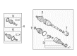
2005 Toyota Corolla Axle Assembly, Passenger Side
Part Number: 43410-02310$452.63 MSRP: $663.33You Save: $210.70 (32%)Product Specifications- Other Name: Shaft Assembly, Front Drive; CV Axle Assembly, Front Right; GSP Cv Axle; Axle Shaft; Axle; Shaft Assembly, Front Drive, Passenger Side; CV Axle Assembly
- Position: Passenger Side
- Part Name Code: 43410
- Item Weight: 20.20 Pounds
- Item Dimensions: 49.9 x 6.2 x 6.1 inches
- Condition: New
- Fitment Type: Direct Replacement
- SKU: 43410-02310
- Warranty: This genuine part is guaranteed by Toyota's factory warranty.
2005 Toyota Corolla Axle Shaft
Looking for affordable OEM 2005 Toyota Corolla Axle Shaft? Explore our comprehensive catalogue of genuine 2005 Toyota Corolla Axle Shaft. All our parts are covered by the manufacturer's warranty. Plus, our straightforward return policy and speedy delivery service ensure an unparalleled shopping experience. We look forward to your visit!
2005 Toyota Corolla Axle Shaft Parts Q&A
- Q: How to service and repair the axle shaft on 2005 Toyota Corolla?A: To start repairing the front drive shaft you need to drain manual transaxle oil at 39 Nm and automatic transaxle fluid at 18 Nm. Separate the engine under cover left side from the front wheel. Begin loosening the hub nut on the left axle with Special Service Tool: 09930-00010 and a hammer. Ensure to fully separate the staked part without damaging the screw of the drive shaft. From the shock absorber assembly front LH, set apart the stabilizer link assembly LH. Apply 6mm hexagon wrench contact only when the joint stud rotates with the nut. Disconnect the speed sensor front LH and its flexible hose off the shock absorber front LH and steering knuckle using Special Service Tool 09628-62011. Afterward separate the tie rod end sub-assembly LH from the steering knuckle. Using a plastic hammer remove the front suspension arm sub-assembly lower No.1 LH from the lower ball joint and carefully disconnect the front drive shaft assembly LH from the front axle assembly LH without damaging the boot and speed sensor rotor. With Special Service Tool 09520-01010, 09520-24010 (09520-32040) remove the front drive shaft assembly LH rubber seal while avoiding damage to its components. When needed push the claw attachment of the Special Service Tool into the part to facilitate the removal process. To avoid hub bearing breakdown we should clamp the front axle assembly with Special Service Tool: 09608-16042 (09608-02021, 09608-02041). Check the outside end of the LH drive shaft for movement and check the inside joint moves freely while inspecting the boot area without tilting the assembly. Reverse pliers should unfasten the inboard joint boot LH No.2 clamp. Side cutters should cut through the inboard joint boot LH clamp before you detach the boot from the inboard joint sub-assembly on the left. Disassemble the inboard joint sub-assembly LH by cleaning its old grease and removing it from the outboard joint shaft assembly. Use a snap ring expander to take out the inner LH shaft snap ring while marking both the outboard joint shaft assembly and tripod joint assembly for remotion. Put the assembly and tripod together using a brass bar and hammer without striking the roller. Split the setting clamp to extract the drive shaft damper from the unit. Push and turn a screwdriver into the front drive shaft LH hole snap ring to remove it along with Special Service Tool: 09950-00020 to take out the dust cover LH. Set the LH dust cover in position using Special Service Tool: 09527-10011 and a press without breaking it. Set the drive shaft damper at 438 to 442 mm (17.24 to 17.40 inch) distance and bolt down its setting clamp. Adjust the damper clearance with Special Service Tool: 09240-00020 (09242-00150). Instal the left-hand inboard joint assembly according to specifications while shielding the spline with vinyl tape to protect boots from damage then secure the left-hand boot and clamps at their adjusted settings. Check for boot damage and play as you repeat the inspection of the front drive shaft assembly LH. Before installing the LH assembly apply ATF or gear oil on the spline and fit its parts together properly with the correct installed hole ring. Follow all steps above to reassemble the right-hand front drive shaft component. Place the left front axle assembly first and then tighten the front suspension arm sub-assembly to 89 Nm (66 ft. lbs.) while avoiding harm to the hub boot and speed sensor components for correct fit. Add the tie rod end sub-assembly and new cotter pin with 49 Nm (36 ft. lbs.). Fit the front speed sensor LH with 29 Nm of torque onto the steering knuckle while applying 8.0 Nm to the threads. Install the sensor after cleaning it and unwinding the wire to avoid twisting. As the final step install the front stabilizer link assembly LH with 74Nm torque force then apply 216Nm to the new LH hub nut. Use a chisel and hammer to stake the nut afterward install the front wheel with 103Nm torque force. Check and refill the transaxle oil reservoir and test the automatic transaxle fluid. Also measure front wheel alignment angles and test ABS speed sensor response.
Related 2005 Toyota Corolla Parts
 2005 Toyota Corolla CV Joint
 2005 Toyota Corolla CV Boot
 2005 Toyota Corolla Shock Absorber
 2005 Toyota Corolla Steering Knuckle
 2005 Toyota Corolla Axle Beam Mount
 2005 Toyota Corolla Bump Stop
 2005 Toyota Corolla Coil Spring Insulator
 2005 Toyota Corolla Shock And Strut Mount
 2005 Toyota Corolla Sway Bar Bracket
 2005 Toyota Corolla Sway Bar Bushing
 2005 Toyota Corolla Sway Bar Kit
 2005 Toyota Corolla Transfer Case Output Shaft Snap Ring