×
ToyotaParts- Hello
- Login or Register
- Quick Links
- Live Chat
- Track Order
- Parts Availability
- RMA
- Help Center
- Contact Us
- Shop for
- Toyota Parts
- Scion Parts
My Garage
My Account
Cart
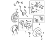
OEM 2006 Toyota Camry Parking Brake Cable
Emergency Parking Brake Release Cable- Select Vehicle by Model
- Select Vehicle by VIN
Select Vehicle by Model
orMake
Model
Year
Select Vehicle by VIN
For the most accurate results, select vehicle by your VIN (Vehicle Identification Number).
6 Parking Brake Cables found

2006 Toyota Camry Front Cable
Part Number: 46410-06030$44.44 MSRP: $61.85You Save: $17.41 (29%)Ships in 1-3 Business DaysProduct Specifications- Other Name: Cable Assembly, Parking; Brake Cable; Cable Assembly, Parking Brake
- Replaces: 46410-33130
- Part Name Code: 46410
- Item Weight: 2.00 Pounds
- Item Dimensions: 16.0 x 12.2 x 3.0 inches
- Condition: New
- Fitment Type: Direct Replacement
- SKU: 46410-06030
- Warranty: This genuine part is guaranteed by Toyota's factory warranty.

2006 Toyota Camry Front Cable
Part Number: 46410-33120$81.87 MSRP: $114.92You Save: $33.05 (29%)Ships in 1-3 Business DaysProduct Specifications- Other Name: Cable Assembly, Parking; Brake Cable; Cable Assembly, Parking Brake
- Part Name Code: 46410
- Item Weight: 2.00 Pounds
- Item Dimensions: 16.0 x 12.2 x 3.0 inches
- Condition: New
- Fitment Type: Direct Replacement
- SKU: 46410-33120
- Warranty: This genuine part is guaranteed by Toyota's factory warranty.

2006 Toyota Camry Cable Assembly, Parking Brake
Part Number: 46430-33100$88.15 MSRP: $123.73You Save: $35.58 (29%)Ships in 1-3 Business DaysProduct Specifications- Other Name: Cable Assembly, Parking; Parking Brake Cable; Brake Cable
- Manufacturer Note: W(VSC)
- Part Name Code: 46430
- Item Weight: 2.40 Pounds
- Item Dimensions: 17.8 x 13.2 x 3.3 inches
- Condition: New
- Fitment Type: Direct Replacement
- SKU: 46430-33100
- Warranty: This genuine part is guaranteed by Toyota's factory warranty.

2006 Toyota Camry Cable Assembly, Parking Brake
Part Number: 46420-33100$81.63 MSRP: $114.58You Save: $32.95 (29%)Ships in 1-3 Business DaysProduct Specifications- Other Name: Cable Assembly, Parking; Parking Brake Cable; Brake Cable
- Manufacturer Note: W(VSC)
- Part Name Code: 46420
- Item Weight: 2.70 Pounds
- Item Dimensions: 18.2 x 12.8 x 3.1 inches
- Condition: New
- Fitment Type: Direct Replacement
- SKU: 46420-33100
- Warranty: This genuine part is guaranteed by Toyota's factory warranty.
 Product Specifications
- Other Name: Cable Assembly, Parking; Brake Cable; Cable Assembly, Parking Brake
- Replaces: 46430-33090
- Part Name Code: 46430
- Item Weight: 2.30 Pounds
- Item Dimensions: 18.1 x 13.8 x 3.2 inches
- Condition: New
- Fitment Type: Direct Replacement
- SKU: 46430-06050
- Warranty: This genuine part is guaranteed by Toyota's factory warranty.
- Product Specifications
- Other Name: Cable Assembly, Parking; Brake Cable; Cable Assembly, Parking Brake
- Replaces: 46420-33090
- Part Name Code: 46420
- Item Weight: 2.60 Pounds
- Item Dimensions: 18.0 x 12.8 x 3.2 inches
- Condition: New
- Fitment Type: Direct Replacement
- SKU: 46420-06050
- Warranty: This genuine part is guaranteed by Toyota's factory warranty.
2006 Toyota Camry Parking Brake Cable
Looking for affordable OEM 2006 Toyota Camry Parking Brake Cable? Explore our comprehensive catalogue of genuine 2006 Toyota Camry Parking Brake Cable. All our parts are covered by the manufacturer's warranty. Plus, our straightforward return policy and speedy delivery service ensure an unparalleled shopping experience. We look forward to your visit!
2006 Toyota Camry Parking Brake Cable Parts Q&A
- Q: How to replace Parking Brake Cable Assembly No. 1 on 2006 Toyota Camry?A: The procedure to substitute Parking Brake Cable Assembly No. 1 requires removal of the front door scuff plate LH, cowl side trim sub-assembly LH, instrument panel sub-assembly upper, instrument panel insert sub-assembly lower LH, console panel upper rear, console box carpet, rear console box, instrument panel ash receptacle assembly, console panel upper, console box front, air duct rear No.1, air duct rear No.2, console box duct No.1, shift lever shaft housing assembly, and yawrate sensor (with VSC). To access the pedal type parking brake, start by loosening the turn buckle from parking brake cable assembly No.1 and disconnecting it from assembly No.4. Continue with console box bracket No.2 bolt removal and the lock nut and adjusting nut extraction before removing the clip and disconnecting cable No.1 at the parking brake control pedal assembly. The next step requires extraction of the 2 nuts together with 2 bolts alongside a clip and parking brake cable assembly No.1. The lever type brake requires removal of adjusting and lock nuts from parking brake cable assembly No.1 before using 2 bolts to disconnect the console box mounting bracket No.2 and separating parking brake cable No.1 from the equalizer. The installation of pedal type parking brake cable assembly No.1 requires 2 nuts, 2 bolts and a clip to connect it with the parking brake control pedal assembly through an adjusting nut and lock nut which should be torqued to 5.4 Nm (55 kgf-cm, 48 inch lbs.). Use 2 bolt fixtures to mount bracket No.2 for the console box while applying 12.5 Nm (128 kgf-cm, 9 ft. lbs.) torque followed by turning the buckle tight before connecting assembly No.1 to No.4 with 5.4 Nm (55 kgf-cm, 48 inch lbs.). To install the lever-type system of parking brake cable assembly No.1 position it with two bolts to the parking brake equalizer then tighten the bolts to 23 Nm (235 kgf-cm, 17 ft. lbs.), next attach console box mounting bracket No.2 using two bolts to a 12.5 Nm (128 kgf-cm, 9 ft. lbs.) torque specification before connecting the cable assembly Number One to the parking brake lever assembly through the adjusting nut and lock nut while maintaining a torque of 5.0 Nm (51 kgf-cm, 44 inch lbs.). The technicians need to reinstall the yawrate sensor (with VSC) and the shift lever shaft housing assembly before adding the console box duct No.1 and the air duct rear No.2 and No.1 and the console box front, console panel upper, instrument panel ash receptacle assembly, rear console box, console box carpet, console panel upper rear, instrument panel insert sub-assembly lower LH and instrument panel sub-assembly upper, cowl side trim sub-assembly LH and front door scuff plate LH. The last task requires checking parking brake pedal travel for pedal type systems alongside performing lever type parking brake lever travel inspection and conducting yawrate sensor zero point calibration using VSC.
Related 2006 Toyota Camry Parts
 2006 Toyota Camry Wheel Bearing
 2006 Toyota Camry Wheel Hub
 2006 Toyota Camry Wheel Stud
 2006 Toyota Camry Brake Pad Set
 2006 Toyota Camry Backing Plate
 2006 Toyota Camry Brake Caliper Bracket
 2006 Toyota Camry Brake Disc
 2006 Toyota Camry Brake Shoe Set
 2006 Toyota Camry Hydraulic Hose
 2006 Toyota Camry Parking Brake Shoe
 2006 Toyota Camry Wheel Cylinder
 2006 Toyota Camry Wheel Cylinder Repair Kit