×
ToyotaParts- Hello
- Login or Register
- Quick Links
- Live Chat
- Track Order
- Parts Availability
- RMA
- Help Center
- Contact Us
- Shop for
- Toyota Parts
- Scion Parts
My Garage
My Account
Cart
OEM 2006 Toyota Avalon Water Pump
H2O Pump- Select Vehicle by Model
- Select Vehicle by VIN
Select Vehicle by Model
orMake
Model
Year
Select Vehicle by VIN
For the most accurate results, select vehicle by your VIN (Vehicle Identification Number).
1 Water Pump found


 Product Specifications
- Other Name: Pump Assembly, Water; Engine Water Pump; Water Pump Assembly; Pump Assembly, Engine Water
- Manufacturer Note: (L)
- Replaces: 16100-39456, 16100-09440, 16100-09441, 16100-39455
- Part Name Code: 16100
- Item Weight: 4.20 Pounds
- Item Dimensions: 14.4 x 8.4 x 6.3 inches
- Condition: New
- Fitment Type: Direct Replacement
- SKU: 16100-09442
- Warranty: This genuine part is guaranteed by Toyota's factory warranty.
2006 Toyota Avalon Water Pump
Looking for affordable OEM 2006 Toyota Avalon Water Pump? Explore our comprehensive catalogue of genuine 2006 Toyota Avalon Water Pump. All our parts are covered by the manufacturer's warranty. Plus, our straightforward return policy and speedy delivery service ensure an unparalleled shopping experience. We look forward to your visit!
2006 Toyota Avalon Water Pump Parts Q&A
- Q: How to replace the water pump assembly on 2006 Toyota Avalon?A: The water pump replacement for (2GR-FE) starts by draining engine coolant then follows with front wheel RH, engine under cover RH, V-bank cover sub-assembly, engine moving control rod, engine mounting control bracket, and engine mounting bracket front No.1 LH removal. The service procedure begins with removing the fan and generator V belt while separating the radiator hose outlet and continuing with the water inlet housing removal after separating the water hose and extracting its 2 bolts and nut and water inlet housing. Due to the removal process separate both the water inlet housing gasket No.1 and water outlet pipe O-ring. To remove the crankshaft pulley operators need Special Service Tools: 09213-70011 and its counterpart 09213-70020 together with 09330-00021, 09950-50013, and its relevant components 09951-05010, 09952-05010, 09953-05020, 09954-05021. To remove the water pump pulley employ Special Service Tool: 09960-10010 (09962-01000, 09963-00700) which will help you keep control while you loosen the four bolts. Remove idler pulley sub-assembly No.2 while paying attention because its bolt operates with left-hand threading. disconnect the vane pump assembly then detach the water pump assembly through 16 bolt removal along with the assembly and gasket. Install the new water pump gasket together with the water pump assembly using 16 bolts and torque them to 21 Nm (214 kgf-cm, 15 ft. lbs.) for bolt A and 9.1 Nm (93 kgf-cm, 81 inch lbs.) for bolts B and C. Replace or properly secure the 2 C bolts with new adhesive 1344 (Part No.08833-00080). You must avoid applying oil on the threads of the A bolts. The installation sequence continues with the vane pump assembly then the idler pulley sub-assembly No.2 where the technician should tighten the left-hand threaded bolt to 43 Nm (438 kgf-cm, 32 ft. lbs.) and set the idler pulley cover plate No.2. The four bolts of the water pump pulley need temporary installation while using Special Service Tool 09960-10010 (09962-01000, 09963-00700) to tighten the bolts to 21Nm (214 kgf-cm, 15 ft. lbs.). Follow the installation procedure using the identical special service tools to install the crankshaft pulley. Put the water inlet housing in place by setting it between new gasket No.1 of water inlet housing and O-ring of water outlet pipe then torque at 10 Nm (102 kgf-cm, 7 ft-lbs) while preventing O-ring entrapment. The installation procedure includes the radiator hose outlet followed by the fan and generator V belt prior to engine mounting bracket front No.1 LH and then engine mounting control bracket and engine moving control rod followed by the V-bank cover sub-assembly. Insert engine coolant before reattaching the engine under cover RH and front wheel RH while checking for any leaking points. Examine the water pump drain hole under visual inspection to check coolant leakage but also rotate the pulley to confirm the bearing moves quietly without any roughness; change the water pump before it shows signs of bearing distress.
Related 2006 Toyota Avalon Parts
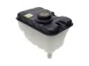 2006 Toyota Avalon Coolant Reservoir
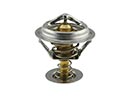 2006 Toyota Avalon Thermostat
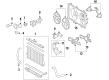
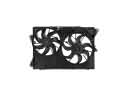 2006 Toyota Avalon Cooling Fan Assembly
 2006 Toyota Avalon Fan Blade
 2006 Toyota Avalon Fan Motor
 2006 Toyota Avalon Fan Shroud
 2006 Toyota Avalon Radiator Cap
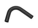 2006 Toyota Avalon Radiator Hose
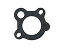 2006 Toyota Avalon Thermostat Gasket
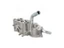 2006 Toyota Avalon Thermostat Housing
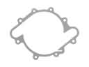 2006 Toyota Avalon Water Pump Gasket
 2006 Toyota Avalon Water Pump Pulley