×
ToyotaParts- Hello
- Login or Register
- Quick Links
- Live Chat
- Track Order
- Parts Availability
- RMA
- Help Center
- Contact Us
- Shop for
- Toyota Parts
- Scion Parts
My Garage
My Account
Cart
OEM 2006 Scion tC Rack And Pinion
Steering Rack And Pinion- Select Vehicle by Model
- Select Vehicle by VIN
Select Vehicle by Model
orMake
Model
Year
Select Vehicle by VIN
For the most accurate results, select vehicle by your VIN (Vehicle Identification Number).
1 Rack And Pinion found

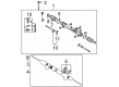
2006 Scion tC Gear Assembly
Part Number: 44200-21123$722.42 MSRP: $1058.70You Save: $336.28 (32%)Ships in 1-3 Business DaysProduct Specifications- Other Name: Link Assembly, Power Steering; Rack and Pinion Assembly; Steering Gearbox; Steering Gear Assembly
- Replaces: 44200-21122, 44200-21120, 44200-21121
- Part Name Code: 44200
- Item Weight: 22.90 Pounds
- Item Dimensions: 51.2 x 10.4 x 6.6 inches
- Condition: New
- Fitment Type: Direct Replacement
- SKU: 44200-21123
- Warranty: This genuine part is guaranteed by Toyota's factory warranty.
2006 Scion tC Rack And Pinion
Looking for affordable OEM 2006 Scion tC Rack And Pinion? Explore our comprehensive catalogue of genuine 2006 Scion tC Rack And Pinion. All our parts are covered by the manufacturer's warranty. Plus, our straightforward return policy and speedy delivery service ensure an unparalleled shopping experience. We look forward to your visit!
2006 Scion tC Rack And Pinion Parts Q&A
- Q: How to remove the Rack And Pinion on 2006 Scion tC?A: A proper removal of the rack and pinion starts with straightening the front wheels and draining power steering fluid. Starting the process requires the elimination of the silencer sheet followed by disconnecting the No. 2 rack and pinion intermediary assembly by using a seat belt to stop the steering wheel from rotating while performing markings on the components before removing the bolt. Start this procedure by detaching the No. 1 rack and pinion column hole cover assembly and removing the front wheel followed by stripping the engine under cover panels from the left and right sides. Both tie rod end sub-assemblies must be separated while also removing the bolt that joins the pressure feed tube assembly along with the tube clamp. Using Special Service Tool: 09023-12701 disconnects the pressure feed tube. Caretakers must separate front stabilizer link assemblies from both sides while disassembling front No. 1 suspension arm sub-assemblies from both sides. The removal process requires unmounting the front floor panel brace as well as the center exhaust pipe assembly, hood sub-assembly, and No. 1 engine cover sub-assembly. The engine should be suspended while technicians remove the No. 1 hook through the extraction of its two bolts. The front suspension crossmember sub-assembly requires removal of four bolts that separate the center member and disconnect engine mounting insulator rear from the crossmember before using a transmission jack to support the crossmember and unbolting brackets from both sides. The procedure ends with removal of the rack and pinion column hole cover sub-assembly followed by intermediate shaft and pinion shaft marking and power steering link assembly removal by disassembling all 4 bolts and 4 nuts without rotating the nuts during bolt loosening.
Related 2006 Scion tC Parts
 2006 Scion tC Steering Wheel
 2006 Scion tC Power Steering Pump
 2006 Scion tC Drag Link
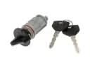 2006 Scion tC Ignition Lock Cylinder
 2006 Scion tC Power Steering Hose
 2006 Scion tC Power Steering Reservoir
 2006 Scion tC Rack and Pinion Boot
 2006 Scion tC Steering Column
 2006 Scion tC Steering Shaft
 2006 Scion tC Tie Rod End