×
ToyotaParts- Hello
- Login or Register
- Quick Links
- Live Chat
- Track Order
- Parts Availability
- RMA
- Help Center
- Contact Us
- Shop for
- Toyota Parts
- Scion Parts
My Garage
My Account
Cart
OEM 2005 Scion tC Rack And Pinion
Steering Rack And Pinion- Select Vehicle by Model
- Select Vehicle by VIN
Select Vehicle by Model
orMake
Model
Year
Select Vehicle by VIN
For the most accurate results, select vehicle by your VIN (Vehicle Identification Number).
1 Rack And Pinion found

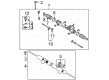
2005 Scion tC Gear Assembly
Part Number: 44200-21123$722.42 MSRP: $1058.70You Save: $336.28 (32%)Ships in 1-3 Business DaysProduct Specifications- Other Name: Link Assembly, Power Steering; Rack and Pinion Assembly; Steering Gearbox; Steering Gear Assembly
- Replaces: 44200-21122, 44200-21120, 44200-21121
- Part Name Code: 44200
- Item Weight: 22.90 Pounds
- Item Dimensions: 51.2 x 10.4 x 6.6 inches
- Condition: New
- Fitment Type: Direct Replacement
- SKU: 44200-21123
- Warranty: This genuine part is guaranteed by Toyota's factory warranty.
2005 Scion tC Rack And Pinion
Looking for affordable OEM 2005 Scion tC Rack And Pinion? Explore our comprehensive catalogue of genuine 2005 Scion tC Rack And Pinion. All our parts are covered by the manufacturer's warranty. Plus, our straightforward return policy and speedy delivery service ensure an unparalleled shopping experience. We look forward to your visit!
2005 Scion tC Rack And Pinion Parts Q&A
- Q: How to install a Rack and Pinion steering system on 2005 Scion tC?A: Begin power steering rack and pinion installation by applying power steering fluid to a new O-ring before installing it to the rack and pinion. Secondly expand a new oil seal with your fingers but be careful not to over-expand it when possible. The seal needs power steering fluid coating before you install it to the rack and pinion while adjusting it. Use lithium molybdenum disulfide grease to coat the rack teeth ends before installment of Special Service Tool: 09631-20102 onto the rack and pinion treated with power steering fluid followed by attaching the rack housing to the rack and pinion after tool removal. Before installing a new cylinder end stopper oil seal onto the RH power steering rack and pinion side, first apply power steering fluid to its lip. Then, install it correctly without causing damage. First remove the vinyl tape then soak a new cylinder end stopper O-ring with power steering fluid before installing it to the cylinder end stopper. Afterward install a new cylinder end stopper bush with molybdenum disulfide lithium base grease applied to its inner section. Finally use Special Service Tool: 09631-20120 to mount the cylinder end stopper to the rack housing while torquing up to 122 Nm (1,244 kgf-cm, 90 ft. lbs.). The rack housing requires installation of Special Service Tool: 09631-12071 (09633-00010) while applying a vacuum at 53 kPa (398 mmHg, 15.65 inch Hg) for approximately 30 seconds to perform the air tightness test. Install the power steering control valve upper oil seal by using tools 09950-70010 (09951-07150), 09950-60010 (09952-06010, 09951-00180, 09951-00300) and a press together with molybdenum disulfide lithium base grease applied to the control valve upper bearing and the oil seal lip coated with power steering fluid while following correct installation direction. The power steering control valve processing requires four new valve spacers that must be expanded before receiving power steering fluid application for installation on the control valve along with complete fluid coating of the valve before its insertion inside the valve housing. Be cautious during installation to avoid damaging either valve spacers or oil seal lip surfaces. The rack housing accepts the control valve housing with a new gasket and requires installation through two bolts with 18 Nm (185 kgf-cm, 13 ft. lbs.) torque. Apply molybdenum disulfide lithium base grease to both the compression spring and the rack guide contact surface and power steering rack and pinion. Install the rack guide with the compression spring after applying Part No. 08833-00080 or equivalent sealant to 2 or 3 threads of the rack guide spring cap then secure it with a straight hexagon wrench (24 mm). The installer must check total preload by releasing the rack guide spring cap and torquing it while installing the rack and pinion ends then turning the power steering rack and pinion 10 times with Special Service Tool 09616-00011 to settle the setup. Adjust preload by rotating the control valve until the measurement ranges between 0.9 to 1.6 Nm (9.2 to 16.3 kgf-cm, 8.0 to 14.2 inch lbs.) while loosening and tightening the rack guide spring cap. Then remove the rack and pinion ends from the vehicle. Fit two new claw washers then temporarily fasten the rack ends while applying MP grease to the rack end ball joint and using Special Service Tool: 09922-10010 to construct the rack end sub-assembly (LH side) with a torque setting of 73 Nm (744 kgf-cm, 54 ft. lbs.) utilizing the tool in its correct direction with a torque wrench measured at 345 mm (13.58 inch) fulcrum length. Follow the same procedure for the rack end sub-assembly (RH side) by using the 22 mm wrench and torque tool for the same specifications and then hammer a brass bar on the 2 claw washers before checking for rack hole cleanliness. Apply silicon grease to the small opening inside rack and pinion boot No.2 before placing a new clamp temporarily and mounting the boot into the rack housing groove while avoiding damage. Repeat the installation for rack and pinion boot No.1 while using clamps and pliers and screwdrivers only without distorting or twisting the boots. Install the boot clips using pliers, check that the rack boots expand and contract smoothly with Special Service Tool: 09616-00011, and connect the tie rod end sub-assemblies (LH and RH) by aligning matchmarks and torquing the lock nut after adjusting toe-in. Install the power steering link assembly using Special Service Tool: 09023-38201 for both left and right turn pressure tubes with a torque of 22 Nm (224 kgf-cm, 16 ft. lbs.), then install the power steering link assembly with 4 bolts and 4 nuts at 49 Nm (500 kgf-cm, 36 ft. lbs.). The procedure requires torquing the install bolt of the steering intermediate shaft to 35 Nm (357 kgf-cm, 26 ft. lbs.) after proper matchmark alignment is achieved. Next, install the steering column hole cover sub-assembly No.1 followed by installation of front suspension crossmember sub-assembly with 2 nuts at 133 Nm (1,356 kgf-cm, 98 ft. lbs.). Finish the process by installing crossmember brackets (LH and RH) with designated torque values. Screw in the engine mounting insulator RR and center member using specified torque specifications before securing the No.1 hook by two bolts at 39 Nm (398 kgf-cm, 29 ft. lbs.). The service required Special Service Tool: 09023-12701 to connect front suspension arm sub-assemblies (lower No.1 LH and RH) along with the front stabilizer link assemblies (LH and RH), the pressure feed tube assembly at 41 Nm (414 kgf-cm, 30 ft. lbs.) before securing the tube clamp to the power steering link assembly at 7.8 Nm (80 kgf-cm, 69 inch lbs.). Finally, install the exhaust pipe assembly center, the floor panel brace front, the front wheels at 103 Nm (1,050 kgf-cm, 76 ft. lbs.), and the steering column hole cover sub-assembly No.1, connecting the steering intermediate shaft assembly No.2 with the bolt at 35 Nm (357 kgf-cm, 26 ft. lbs.), then install the column hole cover silencer sheet, engine cover sub-assembly No.1, add power steering fluid, bleed the system, check the fluid level in the reservoir, check for leaks, and install and adjust the hood sub-assembly before inspecting and adjusting the front wheel alignment, and finally install the engine under covers (LH and RH).
Related 2005 Scion tC Parts
 2005 Scion tC Steering Wheel
 2005 Scion tC Power Steering Pump
 2005 Scion tC Drag Link
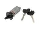 2005 Scion tC Ignition Lock Cylinder
 2005 Scion tC Power Steering Hose
 2005 Scion tC Power Steering Reservoir
 2005 Scion tC Rack and Pinion Boot
 2005 Scion tC Steering Column
 2005 Scion tC Steering Shaft
 2005 Scion tC Tie Rod End