×
ToyotaParts- Hello
- Login or Register
- Quick Links
- Live Chat
- Track Order
- Parts Availability
- RMA
- Help Center
- Contact Us
- Shop for
- Toyota Parts
- Scion Parts
My Garage
My Account
Cart
OEM 2005 Scion tC Power Steering Pump
Power Steering Pump Unit- Select Vehicle by Model
- Select Vehicle by VIN
Select Vehicle by Model
orMake
Model
Year
Select Vehicle by VIN
For the most accurate results, select vehicle by your VIN (Vehicle Identification Number).
1 Power Steering Pump found


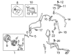
2005 Scion tC Power Steering Pump
Part Number: 44310-20870$361.49 MSRP: $529.76You Save: $168.27 (32%)Ships in 1-3 Business DaysProduct Specifications- Other Name: Pump Assembly, Vane
- Part Name Code: 44320
- Item Weight: 4.30 Pounds
- Item Dimensions: 8.0 x 5.9 x 5.7 inches
- Condition: New
- Fitment Type: Direct Replacement
- SKU: 44310-20870
- Warranty: This genuine part is guaranteed by Toyota's factory warranty.
2005 Scion tC Power Steering Pump
Looking for affordable OEM 2005 Scion tC Power Steering Pump? Explore our comprehensive catalogue of genuine 2005 Scion tC Power Steering Pump. All our parts are covered by the manufacturer's warranty. Plus, our straightforward return policy and speedy delivery service ensure an unparalleled shopping experience. We look forward to your visit!
2005 Scion tC Power Steering Pump Parts Q&A
- Q: How to service and repair the power steering pump on 2005 Scion tC?A: To repair and service power steering pump, take out front wheel, empty the fluid. Disattach different parts such as oil reservoir hose and pressure feed tube assembly. Take the vane pump assembly out and check parts wear. Repack with new seals and make sure that the correct torque is met. Lastly, drain the fluid and test leakages.
Related 2005 Scion tC Parts
 2005 Scion tC Steering Wheel
 2005 Scion tC Rack And Pinion
 2005 Scion tC Drag Link
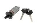 2005 Scion tC Ignition Lock Cylinder
 2005 Scion tC Power Steering Hose
 2005 Scion tC Power Steering Reservoir
 2005 Scion tC Rack and Pinion Boot
 2005 Scion tC Steering Column
 2005 Scion tC Steering Shaft
 2005 Scion tC Tie Rod End