×
ToyotaParts- Hello
- Login or Register
- Quick Links
- Live Chat
- Track Order
- Parts Availability
- RMA
- Help Center
- Contact Us
- Shop for
- Toyota Parts
- Scion Parts
My Garage
My Account
Cart
OEM 2005 Toyota Tundra Crankshaft Seal
- Select Vehicle by Model
- Select Vehicle by VIN
Select Vehicle by Model
orMake
Model
Year
Select Vehicle by VIN
For the most accurate results, select vehicle by your VIN (Vehicle Identification Number).
3 Crankshaft Seals found


2005 Toyota Tundra Rear Main Seal
Part Number: 90311-A0006$53.88 MSRP: $75.00You Save: $21.12 (29%)Ships in 1-2 Business DaysProduct Specifications- Other Name: Seal, Type T Oil; Engine Crankshaft Seal, Rear; Engine Crankshaft Seal Kit; Crankshaft Seal Kit; Oil Seal Set; Crankshaft Seal; Rear Seal; Seal, Engine Rear Oil; Seal
- Manufacturer Note: (L)
- Replaces: 90311-99010
- Part Name Code: 11381A
- Item Weight: 0.70 Pounds
- Item Dimensions: 5.2 x 5.1 x 0.4 inches
- Condition: New
- Fitment Type: Direct Replacement
- SKU: 90311-A0006
- Warranty: This genuine part is guaranteed by Toyota's factory warranty.


2005 Toyota Tundra Rear Main Seal
Part Number: 90311-A0002$31.42 MSRP: $43.73You Save: $12.31 (29%)Ships in 1 Business DayProduct Specifications- Other Name: Seal, Type T Oil; Engine Crankshaft Seal, Rear; Timing Cover Seal; Rear Seal; Seal, Engine Rear Oil
- Manufacturer Note: (L)
- Part Name Code: 11381A
- Item Weight: 0.50 Pounds
- Item Dimensions: 4.9 x 5.1 x 0.4 inches
- Condition: New
- Fitment Type: Direct Replacement
- SKU: 90311-A0002
- Warranty: This genuine part is guaranteed by Toyota's factory warranty.


2005 Toyota Tundra Oil Seal, Front
Part Number: 90311-A0005$19.11 MSRP: $26.60You Save: $7.49 (29%)Ships in 1-3 Business DaysProduct Specifications- Other Name: Seal, Type T Oil; Engine Crankshaft Seal, Front; Timing Cover Gasket; Multi-Purpose Seal; Timing Cover Seal; Crankshaft Seal; Front Seal; Timing Cover Oil Seal; Engine Crankshaft Seal
- Position: Front
- Replaces: 90311-42019, 90311-42007, 90311-42037, 90311-42036
- Part Name Code: 11301C
- Item Weight: 0.50 Pounds
- Item Dimensions: 5.3 x 4.8 x 1.0 inches
- Condition: New
- Fitment Type: Direct Replacement
- SKU: 90311-A0005
- Warranty: This genuine part is guaranteed by Toyota's factory warranty.
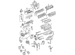
2005 Toyota Tundra Crankshaft Seal
Looking for affordable OEM 2005 Toyota Tundra Crankshaft Seal? Explore our comprehensive catalogue of genuine 2005 Toyota Tundra Crankshaft Seal. All our parts are covered by the manufacturer's warranty. Plus, our straightforward return policy and speedy delivery service ensure an unparalleled shopping experience. We look forward to your visit!
2005 Toyota Tundra Crankshaft Seal Parts Q&A
- Q: How to replace the Crankshaft Seal and complete the associated assembly process on 2005 Toyota Tundra?A: To replace the timing chain cover oil seal when removing the rear timing chain cover apply a screwdriver to gently remove the oil seal while taping the screwdriver tip to avoid damaging the oil pump. Use Special Service Tool: 09226-10010 to tap in a new oil seal until it reaches the timing chain cover edge and apply MP grease to the oil seal lip. Installation of the rear timing chain cover requires the same approach along with care against damaging the crankshaft assembly. The crankshaft position requires adjustment through the crankshaft pulley set bolt until the crankshaft set key reaches its left horizontal position to establish the right angle that avoids piston and valve contact. Install chain tensioner No.2 into position by using a 1.0 mm pin as a stopper and fasten it with a bolt torqued to 19 Nm (194 kgf-cm, 14 ft. lbs.). Place the yellow marked chain links against the camshaft timing gear assembly and camshaft timing sprocket timing marks before installing each camshaft timing gear with its chain to the RH camshafts. Do not use excessive force when installing the 2 camshaft timing gear bolts while gripping the hexagonal camshaft part with a wrench. Tighten the bolts to 100 Nm (1,020 kgf-cm, 74 ft. lbs.) before removing the chain tensioner No.2 pin. The installation of chain vibration damper No.1 requires tightening two bolts to 19 Nm (194 kgf-cm, 14 ft. lbs.). Afterward, position the timing gear set key to match the key groove of the sprocket and place the timing gear onto the crankshaft. The chain tensioner slipper and chain tensioner No.1 installation requires the plunger to be pushed followed by stopper plate clockwise rotation then counterclockwise rotation to secure a 3.5 mm bar before tightening the two bolts to 10 Nm (102 kgf-cm, 7 ft. lbs.). You should turn the crankshaft until the crankshaft set key matches the timing line of the cylinder block when aligning the timing marks to set No.1 cylinder at TDC/compression. Position timing chain No.1 by guiding its yellow mark link into the crankshaft timing sprocket then its orange mark links into both camshaft timing gear assembly and camshaft timing sprocket. The procedure involves installing chain vibration damper No.2 along with idle gear No.1 while applying engine oil to the idle gear shaft No.1. Then temporarily mounting them while lining up the knock pin before using a 10 mm hexagon wrench to tighten the idle gear shaft No.2 to 60 Nm (612 kgf-cm, 44 ft. lbs.) and removing the bar that secures the chain tensioner. An installation procedure requires you to replace the old packing material and install a new O-ring on the LH cylinder head before applying a continuous bead of seal packing (Part No.08826-00080 or equivalent) to specified locations. Install the cover within 3 minutes before tightening the bolts and nuts uniformly to 23 Nm (235 kgf-cm, 17 ft. lbs.). Use new O-rings and install the water inlet onto its gasket while applying soapy water to the ring and joining water by-pass hoses along with radiator and oil cooler hoses. New packing material should be installed within three minutes for the oil pan. Proper spreading and equal torque application must happen to specified bolts and nuts. Fit the new gasket onto the oil strainer before tight installation of oil pan No.2 and its seal packing following the provided time parameters. The crankshaft pulley requires Special Service Tools: 09213-54015 (91651-60855), 09330-00021 for its installation before idler pulleys No.1 and No.2 receive their specified torque values. Correct installation of the cooler compressor and generator and vane pump necessitates avoiding contact with the pulley during the assembly process. For the installation place the oil level gauge guide together with a new O-ring followed by a lubrication of the O-ring with engine oil before fitting the gauge. As the final step of assembly install the cylinder head cover followed by the intake air surge tank along with the air cleaner and fan with fluid coupling and drive belt and radiator and V-bank cover and battery then fill with engine oil and coolant before leak inspection and ignition timing and idle speed verification.
Related 2005 Toyota Tundra Parts
 2005 Toyota Tundra Oil Filter
 2005 Toyota Tundra Camshaft
 2005 Toyota Tundra Oil Pan
 2005 Toyota Tundra Timing Chain Tensioner
 2005 Toyota Tundra Valve Cover Gasket
 2005 Toyota Tundra Crankshaft Thrust Washer Set
 2005 Toyota Tundra Cylinder Head
 2005 Toyota Tundra Cylinder Head Gasket
 2005 Toyota Tundra Drain Plug Washer
 2005 Toyota Tundra Piston
 2005 Toyota Tundra Piston Ring Set
 2005 Toyota Tundra Timing Idler Gear