×
ToyotaParts- Hello
- Login or Register
- Quick Links
- Live Chat
- Track Order
- Parts Availability
- RMA
- Help Center
- Contact Us
- Shop for
- Toyota Parts
- Scion Parts
My Garage
My Account
Cart
OEM 2005 Toyota Sienna Fuel Injector
Gas Injector- Select Vehicle by Model
- Select Vehicle by VIN
Select Vehicle by Model
orMake
Model
Year
Select Vehicle by VIN
For the most accurate results, select vehicle by your VIN (Vehicle Identification Number).
1 Fuel Injector found

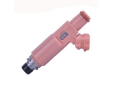
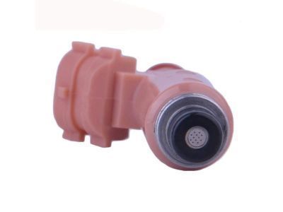
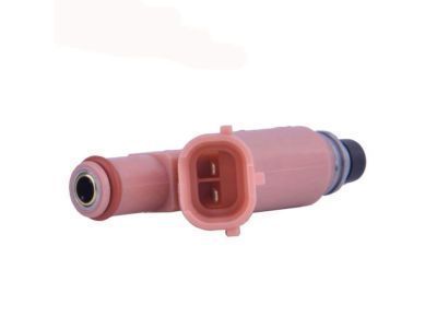
2005 Toyota Sienna Injector Assembly, Fuel
Part Number: 23209-0A020$160.85 MSRP: $227.70You Save: $66.85 (30%)Ships in 1-2 Business DaysProduct Specifications- Other Name: Injector Set, Fuel; Fuel Injector
- Manufacturer Note: (L)
- Part Name Code: 23250
- Item Weight: 0.60 Pounds
- Item Dimensions: 3.5 x 1.9 x 1.4 inches
- Condition: New
- Fitment Type: Direct Replacement
- Require Quantity: 6
- SKU: 23209-0A020
- Warranty: This genuine part is guaranteed by Toyota's factory warranty.
2005 Toyota Sienna Fuel Injector
Looking for affordable OEM 2005 Toyota Sienna Fuel Injector? Explore our comprehensive catalogue of genuine 2005 Toyota Sienna Fuel Injector. All our parts are covered by the manufacturer's warranty. Plus, our straightforward return policy and speedy delivery service ensure an unparalleled shopping experience. We look forward to your visit!
2005 Toyota Sienna Fuel Injector Parts Q&A
- Q: How to replace the fuel injector on 2005 Toyota Sienna?A: The first step to replace the fuel injector requires removing engine coolant and discharging fuel system pressure. Begin by removing the front wiper arm head cap before taking out each front wiper arm (LH and RH), the cowl top ventilator louver sub assembly, the windshield wiper motor assembly alongside the cowl top to cowl brace inner No. 1 by unfastening its 2 bolts. Move to the removal of the cowl top panel sub assembly outer front component by unfastening the wire harness clamp followed by grommet separation and 7 bolt detachment. The servicing technician must first detach the V bank cover sub assembly and air cleaner cap sub assembly and emission control valve set by unplugging the 2 VSV connectors and wire harness clamp and fuel vapor feed hoses and 2 vacuum hoses before removing the clamp and 2 nuts. Start by detaching the throttle motor connector before removing the water bypass hoses and union to check valve hose, ventilation hose and finally the 2 set nuts of the pressure feed tube. Next, remove the 2 engine hunger No. 1 bolts and both surge tank stays. The socket hexagon wrench 8 will unfasten the 4 bolts which allows removal of the gasket from the intake air surge tank. Begin by undoing the bolt and fuel pipe No. 1 from the assembly then remove the fuel pressure pulsation damper followed by all 2 gaskets before completing the separation with the fuel pipe No. 2 union bolt and its remaining 2 gaskets. Unplug all 6 fuel injector connectors after which you can take out the assembly containing 4 bolts and two fuel delivery pipes that hold the 6 fuel injectors in place without allowing them to drop. Disassemble the intake manifold by withdrawing both the 4 delivery pipe No. 1 spacers 1 and the 6 insulators 2 and extracting fuel injectors from their position in the delivery pipe. New grommets must be placed onto fuel injectors before applying a thin layer of spindle oil or gasoline to O-rings which should then be installed onto the injectors. Use spindle oil or gasoline on the fuel delivery pipe O-ring area before inserting the fuel injectors by rotating them into place. The assembly progression starts with installing 6 new insulators and 4 delivery pipe No.1 spacers onto the intake manifold. Then place both fuel delivery pipes with 6 fuel injectors onto the manifold, ensure 4 bolts are installed temporarily while performing smooth rotation tests on the injectors. Secure the 4 bolts to 10 N.m (102 kgf.cm. 7 ft.lbf) torque and link the 6 fuel injector connectors. Start by installing the fuel pipe sub assembly No. 1 with its two new gaskets and the fuel pipe No. 2 union bolt tightened to 33 N.m (331 kgf.cm, 24 ft.lbf) torque, followed by application of 2 new gaskets on the fuel pressure pulsation damper using the same torque value then completing the process with the fuel pipe No. 1 bolt tightened to 20 N.m (199 kgf.cm, 14 ft.lbf). To proceed with the installation install a fresh gasket onto the intake air surge tank followed by tightening the surge tank and emission control valve bracket using 2 nuts at 28 N.m (286 kgf.cm, 21 ft.lbf). Then apply torque to the 4 bolts with a socket hexagon wrench 8 at the same setting before mounting the surge tank stays and engine hunger No. 1 with their respective bolts at 20 N.m (199 kgf.cm, 14 ft.lbf). prostituthe pressure feed tube by fastening two nuts to 7.8 N.m (80 kgf.cm, 69 in.lbf) then follow with the ventilation hose and union to check valve hose connections after which connecting both water bypass hoses before reattaching the throttle motor connector. Final assembly requires installing the emission control valve to 8.0 N.m (82 kgf.cm, 71 in.lbf) together with the air cleaner cap sub assembly followed by adding engine coolant before inspecting for leaks. The installation sequence includes V bank cover sub assembly and cowl top panel sub assembly outer front at 7.5 N.m (76 kgf.cm, 66 in.lbf) along with cowl top to cowl brace inner No. 1 at the same torque, windshield wiper motor assembly, cowl top ventilator louver sub assembly, both front wiper arms (RH and LH), and front wiper arm head cap.


