×
ToyotaParts- Hello
- Login or Register
- Quick Links
- Live Chat
- Track Order
- Parts Availability
- RMA
- Help Center
- Contact Us
- Shop for
- Toyota Parts
- Scion Parts
My Garage
My Account
Cart
OEM 2004 Toyota Sienna Fuel Injector
Gas Injector- Select Vehicle by Model
- Select Vehicle by VIN
Select Vehicle by Model
orMake
Model
Year
Select Vehicle by VIN
For the most accurate results, select vehicle by your VIN (Vehicle Identification Number).
1 Fuel Injector found


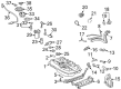
2004 Toyota Sienna Injector Assembly, Fuel
Part Number: 23209-0A020$160.85 MSRP: $227.70You Save: $66.85 (30%)Ships in 1-2 Business DaysProduct Specifications- Other Name: Injector Set, Fuel; Fuel Injector
- Manufacturer Note: (L)
- Part Name Code: 23250
- Item Weight: 0.60 Pounds
- Item Dimensions: 3.5 x 1.9 x 1.4 inches
- Condition: New
- Fitment Type: Direct Replacement
- Require Quantity: 6
- SKU: 23209-0A020
- Warranty: This genuine part is guaranteed by Toyota's factory warranty.
2004 Toyota Sienna Fuel Injector
Looking for affordable OEM 2004 Toyota Sienna Fuel Injector? Explore our comprehensive catalogue of genuine 2004 Toyota Sienna Fuel Injector. All our parts are covered by the manufacturer's warranty. Plus, our straightforward return policy and speedy delivery service ensure an unparalleled shopping experience. We look forward to your visit!
2004 Toyota Sienna Fuel Injector Parts Q&A
- Q: How to replace the fuel injector on 2004 Toyota Sienna?A: The first step to replace a fuel injector consists of draining the engine coolant while also discharging fuel system pressure. Removal of the front wiper arm head cap combined with both front wiper arms (LH and RH) requires the cowl top ventilator louver sub assembly separation alongside the windshield wiper motor assembly followed by the cowl top to cowl brace inner No. 1 with its 2 bolts removed. Proceed to uninstall the cowl top panel sub assembly outer front by disconnecting the wire harness clamp along with the grommet and 7 bolts. Start by detaching the 2 VSV connectors from the emission control valve set along with wire harness clamp, fuel vapor feed hoses, 2 vacuum hoses and finally remove the clamp and 2 nuts. Dismantle the intake air surge tank by disconnecting throttle motor connector while removing water bypass hoses, union to check valve hose and ventilation hose and then disconnecting the 2 set nuts of pressure feed tube and the 2 bolts of engine hunger No. 1 and both surge tank stays. Use a socket hexagon wrench 8 to remove the 4 bolts which allows you to take out the emission control valve bracket and intake air surge tank together with the gasket. The procedure for fuel pipe sub assembly No. 1 separation involves first removing the bolt followed by fuel pipe No. 1, fuel pressure pulsation damper and 2 gaskets before finally taking out the fuel pipe No. 2 union bolt together with 2 gaskets. Unplug all 6 fuel injector connectors before removing the 4 bolts with both fuel delivery pipes and 6 fuel injectors while avoiding accidental dropping. Extract the 4 delivery pipe No. 1 spacers and 6 insulators from the intake manifold before removing the fuel injector from the fuel delivery pipe. Instillation requires new grommets on each fuel injector followed by light spindle oil or gasoline application on fresh O-rings before their placement on each injector point. Begin by applying oil or gasoline to both the O-ring contact areas of the delivery pipe before slowly inserting the fuel injector into the pipe while performing rotations. Install 6 new insulators and 4 delivery pipe No. 1 spacers to the intake manifold, place the 2 fuel delivery pipes and 6 fuel injectors to their mounting position on the manifold, temporarily secure four bolts, then verify the injectors rotate correctly. Apply force of 10 N.m through 4 bolts while installing the 6 fuel injector connectors. Follow the installation of Fuel Pipe Sub Assembly No. 1 with its two gaskets and the Fuel Pipe No. 2 union bolt tightening at 33 N.m (331 kgf.cm, 24 ft.lbf) by adding the fuel pressure pulsation damper which requires a torque of 20 N.m (199 kgf.cm, 14 ft.lbf). Insert a new gasket to the intake air surge tank before securing it with the emission control valve bracket by threading 2 nuts to 28 N.m (286 kgf.cm, 21 ft.lbf). Finally, tighten the 4 bolts to match the original torque. The installation process requires two bolts on surge tank stays No. 2 and No. 1 to achieve 20 N.m (199 kgf.cm, 14 ft.lbf) torque each. Then proceed to install two bolts on the engine hunger No. 1 at 20 N.m (199 kgf.cm, 14 ft.lbf) along with two nuts on the pressure feed tube at 7.8 N.m (80 kgf.cm, 69 in.lbf). Reconnect the throttle motor connector and fasten both water bypass hoses along with the union to check valve hose and ventilation hose. Finally complete the installation with the air cleaner cap sub assembly. Afterward set the emission control valve to 8.0 N.m (82 kgf.cm, 71 in.lbf). The installer must add engine coolant while inspecting for leaks before the equipment sequence continues with V bank cover subassembly, cowl top panel subassembly outer front at 7.5 N.m (76 kgf.cm, 66 in.lbf), cowl top to cowl brace inner No. 1 at the same torque, windshield wiper motor assembly, cowl top ventilator louver subassembly, and both front wiper arms (RH and LH) followed by front wiper arm head cap installation.
Related 2004 Toyota Sienna Parts
 2004 Toyota Sienna Fuel Tank
 2004 Toyota Sienna Gas Cap
 2004 Toyota Sienna Fuel Filter
 2004 Toyota Sienna Fuel Pump
 2004 Toyota Sienna Fuel Filler Hose
 2004 Toyota Sienna Fuel Filler Neck
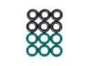 2004 Toyota Sienna Fuel Injector O-Ring
 2004 Toyota Sienna Fuel Pressure Regulator
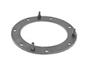 2004 Toyota Sienna Fuel Pump Gasket
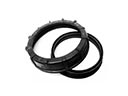 2004 Toyota Sienna Fuel Pump Seal
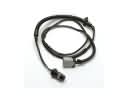 2004 Toyota Sienna Fuel Pump Wiring Harness
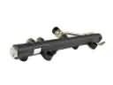 2004 Toyota Sienna Fuel Rail