×
ToyotaParts- Hello
- Login or Register
- Quick Links
- Live Chat
- Track Order
- Parts Availability
- RMA
- Help Center
- Contact Us
- Shop for
- Toyota Parts
- Scion Parts
My Garage
My Account
Cart
OEM 2006 Toyota Sienna Fuel Injector
Gas Injector- Select Vehicle by Model
- Select Vehicle by VIN
Select Vehicle by Model
orMake
Model
Year
Select Vehicle by VIN
For the most accurate results, select vehicle by your VIN (Vehicle Identification Number).
1 Fuel Injector found


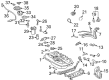
2006 Toyota Sienna Injector Assembly, Fuel
Part Number: 23209-0A020$160.85 MSRP: $227.70You Save: $66.85 (30%)Ships in 1-2 Business DaysProduct Specifications- Other Name: Injector Set, Fuel; Fuel Injector
- Manufacturer Note: (L)
- Part Name Code: 23250
- Item Weight: 0.60 Pounds
- Item Dimensions: 3.5 x 1.9 x 1.4 inches
- Condition: New
- Fitment Type: Direct Replacement
- Require Quantity: 6
- SKU: 23209-0A020
- Warranty: This genuine part is guaranteed by Toyota's factory warranty.
2006 Toyota Sienna Fuel Injector
Looking for affordable OEM 2006 Toyota Sienna Fuel Injector? Explore our comprehensive catalogue of genuine 2006 Toyota Sienna Fuel Injector. All our parts are covered by the manufacturer's warranty. Plus, our straightforward return policy and speedy delivery service ensure an unparalleled shopping experience. We look forward to your visit!
2006 Toyota Sienna Fuel Injector Parts Q&A
- Q: How to service and repair the fuel injector on 2006 Toyota Sienna?A: The first step for fuel injector servicing includes draining the engine coolant before the fuel system needs discharging the pressure. First remove the head cap from both front wiper arms (LH and RH) and cowl top ventilator louver subassembly as well as the windshield wiper motor assembly. The service begins with removing two bolts holding the cowl brace inner section of the No. 1 cowl top before proceeding to uninstall the seven bolts from the cowl top panel sub-assembly front outer section while also removing the wire harness clamp and grommet. First detach the emission control valve set by unplugging the VSV connector and wire harness clamp then removing the fuel vapor feed hoses and vacuum hoses and dissolving the two V-bank cover sub-assembly nuts. Detach the surge tank from intake air by removing different hoses and using a socket hexagon wrench 8 to remove 4 bolts while also taking out the two bolts from the No. 1 surge tank stays and engine hanger. The procedure requires unfastening the bolt and removing both the No. 1 fuel pipe and the fuel pressure pulsation damper together with the gaskets. The procedure for the fuel injector assembly includes disconnecting the 6 fuel injector connectors followed by removing the 4 bolts from the assembly with the 2 fuel delivery pipes containing 6 fuel injectors. Subsequently one can extract 4 delivery pipe No. 1 spacers ( 1) and 6 insulators ( 2) from the intake manifold and remove the fuel injectors from the fuel delivery pipe. The installation process requires new fuel injector grommets in addition to oil or gas application on fresh O-rings before placing them properly. The fuel injectors should enter the delivery pipe without rotating the O-rings before checking the free motion of each injector. Place the intake manifold with 6 new insulators and 4 delivery pipe No. 1 spacers and then mount 2 fuel delivery pipes along with 6 fuel injectors before securing temporary 4 bolts to 10 N.m (102 kgf.cm, 7 ft.lbf) torque limit. The installation of No. 1 fuel pipe sub-assembly requires new gaskets and bolts that need tightening to specified torque values after connecting the 6 fuel injector connectors. Mount the intake air surge tank with new gasket installation alongside the emission control valve bracket while torquing all related hardware to specific specifications. The maintenance procedure requires installation of emission control valve sets while adding engine coolant and checking for leakage of both fuel and engine coolant before reinstalling the V-bank cover sub-assembly and cowl top panel sub-assembly outer front units. The service ends by reinstalling the V-bank cover sub-assembly and both front wiper arms but starting with the cowl top panel sub-assembly outer front, No. 1 cowl top to cowl brace inner, windshield wiper motor assembly, cowl top ventilator louver sub-assembly before placing the front wiper arm head cap.
Related 2006 Toyota Sienna Parts
 2006 Toyota Sienna Fuel Tank
 2006 Toyota Sienna Gas Cap
 2006 Toyota Sienna Fuel Filter
 2006 Toyota Sienna Fuel Pump
 2006 Toyota Sienna Fuel Filler Hose
 2006 Toyota Sienna Fuel Filler Neck
 2006 Toyota Sienna Fuel Injector O-Ring
 2006 Toyota Sienna Fuel Pressure Regulator
 2006 Toyota Sienna Fuel Pump Gasket
 2006 Toyota Sienna Fuel Pump Seal
 2006 Toyota Sienna Fuel Pump Wiring Harness
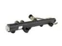 2006 Toyota Sienna Fuel Rail