×
ToyotaParts- Hello
- Login or Register
- Quick Links
- Live Chat
- Track Order
- Parts Availability
- RMA
- Help Center
- Contact Us
- Shop for
- Toyota Parts
- Scion Parts
My Garage
My Account
Cart
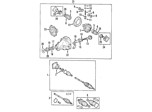
Rear Propeller Shaft
2005 Toyota Sienna Drive Shaft, Universal Joint
Currently shopping for
2005 Toyota Sienna
Change VehicleVehicle Options
6 Cyl 3.3 L GASVehicle Options
6 Cyl 3.3 L GASCategories Close X
Currently selected
Driveline & Axles
Other Categories
A/C & Heating
Air & Fuel Delivery
Belts & Cooling
Body & Hardware
Brakes
Charging & Starting
Electrical
Emission Control & Exhaust
Engine
Headlights & Lighting
Interior & Exterior Trim
Maintenance & Lubrication
Steering
Suspension
Transmission
How to use OE catalog
Diagram (1 of 1): Rear Axle
Sort by:
Ref No.
Ref No.
Part No. & Part Description
Price & Qty.
Part No. &
Part Description
Part Description
- 1
 MSRP: $581.49 Your Price: $396.781
- 2
 MSRP: $363.32 Your Price: $254.471
- 3
 MSRP: $370.53 Your Price: $259.521
- 4
 MSRP: $62.53 Your Price: $44.921
- 5

 MSRP: $70.01 Your Price: $50.301
- 6
 MSRP: $14.29 Your Price: $10.271
- 7

 MSRP: $416.49 Your Price: $291.70
- 8
 MSRP: $152.18 Your Price: $108.421
- 9
 MSRP: $9.46 Your Price: $6.80
- 10
 MSRP: $110.43 Your Price: $78.671
- 11

 MSRP: $3.31 Your Price: $2.381
- 12
 MSRP: $33.92 Your Price: $24.371
- 13
 MSRP: $1260.47 Your Price: $860.091
- 14

 MSRP: $6.64 Your Price: $4.771
- 15

 MSRP: $77.00 Your Price: $55.321
- 16

 MSRP: $22.94 Your Price: $16.481
- 17
 MSRP: $71.51 Your Price: $51.371
- 18
 MSRP: $9.96 Your Price: $7.16
- 19

 MSRP: $16.45 Your Price: $11.821
- 20

 MSRP: $107.10 Your Price: $76.301
- 21
 MSRP: $3052.24 Your Price: $2082.711
- 22
 MSRP: $697.28 Your Price: $475.791
- 23
 MSRP: $317.61 Your Price: $222.451
- 24
 MSRP: $252.15 Your Price: $176.601
- 25

 MSRP: $15.62 Your Price: $11.221
- 26


 MSRP: $20.11 Your Price: $14.451


 MSRP: $231.86 Your Price: $163.781

 MSRP: $1506.32 Your Price: $1027.841
")
") 90080-10294
90080-10294
Bolt, NO.2 (For Propeller Shaft & Differential Setting)- Production Date: 01/2003-12/2006
- Fitting Vehicle Options: MCL25
- Require Quantity: 4
- Package Quantity: 1
- Part Name Code: 37100D
MSRP: $4.47 Your Price: $3.21
 35427-06010
Piston, B-3 Accumulator- Part Notes: (L)
- Production Date: 01/2003-12/2006
- Fitting Vehicle Options: MCL2#
- Part Name Code: 35427K
- Replaced By: 35427-21010
MSRP: $61.69 Your Price: $44.32
")
") 90560-10107
90560-10107
Washer, NO.2 (For Propeller Shaft & Differential Setting)- Production Date: 01/2003-12/2006
- Fitting Vehicle Options: MCL25
- Require Quantity: 4
- Package Quantity: 1
- Part Name Code: 37100F
- Replaced By: 90560-10102
MSRP: $3.14 Your Price: $2.26
")
") 90178-10013
90178-10013
Nut, NO.2 (For Propeller Shaft & Differential Setting)- Production Date: 01/2003-12/2006
- Fitting Vehicle Options: MCL25
- Require Quantity: 4
- Package Quantity: 1
- Part Name Code: 37100E
MSRP: $2.48 Your Price: $1.78
OEM 2005 Toyota Sienna Parts for Rear Propeller Shaft
Genuine 2005 Toyota Sienna parts are produced by Toyota with the official design and standards, thus they ensure a high quality throughout the production process. OEM parts are the ideal choice for people looking for new Rear Propeller Shaft parts. With our competitive prices, we offer 2005 Toyota Sienna Drive Shaft, Universal Joint that fit tight budgets, while still including the manufacturer warranties, a hassle-free returns policy and quick shipping options.
Drive Shaft Installation and Repair Tips for 2005 Toyota Sienna
- Q: How to overhaul the rear drive shaft on 2005 Toyota Sienna?A: In order to replace the rear drive shaft (4WD), dismantle the rear wheel, exhaust pipe assembly tail, and rear LH speed sensor. Unscrew the rear axle shaft LH nut, unscrew the drive shaft, and test whether there is any play. Change boots, grease, and install parts, with no harm.