×
ToyotaParts- Hello
- Login or Register
- Quick Links
- Live Chat
- Track Order
- Parts Availability
- RMA
- Help Center
- Contact Us
- Shop for
- Toyota Parts
- Scion Parts
My Garage
My Account
Cart
OEM 2004 Toyota Sienna Drive Shaft
Axle Shaft- Select Vehicle by Model
- Select Vehicle by VIN
Select Vehicle by Model
orMake
Model
Year
Select Vehicle by VIN
For the most accurate results, select vehicle by your VIN (Vehicle Identification Number).
1 Drive Shaft found


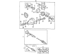
2004 Toyota Sienna Drive Shaft
Part Number: 37100-45010$1027.84 MSRP: $1506.32You Save: $478.48 (32%)Ships in 1-3 Business DaysProduct Specifications- Other Name: Shaft Assembly, Propeller; Driveshaft; Shaft Assembly, Propeller W/Center Bearing
- Part Name Code: 37100
- Item Weight: 40.40 Pounds
- Item Dimensions: 109.2 x 9.3 x 8.2 inches
- Condition: New
- Fitment Type: Direct Replacement
- SKU: 37100-45010
- Warranty: This genuine part is guaranteed by Toyota's factory warranty.
2004 Toyota Sienna Drive Shaft
Looking for affordable OEM 2004 Toyota Sienna Drive Shaft? Explore our comprehensive catalogue of genuine 2004 Toyota Sienna Drive Shaft. All our parts are covered by the manufacturer's warranty. Plus, our straightforward return policy and speedy delivery service ensure an unparalleled shopping experience. We look forward to your visit!
2004 Toyota Sienna Drive Shaft Parts Q&A
- Q: How to overhaul the rear drive shaft on 2004 Toyota Sienna?A: The procedure for repairing the rear drive shaft (4WD) starts with wheel removal then unfastening the exhaust pipe assembly tail and speed sensor rear LH unit while safeguarding against sensor damage and exclusion of debris. The removal of the rear axle shaft LH nut requires Special Service Tool: 09930-00010 and a hammer operation to unstake the nut followed by brake-application and the nut's complete removal. Conduct the disconnect process of the rear drive shaft assembly LH by marking drive shaft components and differential side gear shaft while removing 4 nuts along with washers to detach the drive shaft from the axle carrier. When installing the rear axle assembly LH take care not to damage the ABS speed sensor rotor serration while using Special Service Tool: 09608-16042 to hold the hub bearing if needed. While inspecting the LH rear drive shaft assembly you should check for loose joints and evaluate the condition of its boot. Open the inboard joint boot No.2 clamp as well as the inboard joint boot before you pull out the rear drive shaft inboard joint assembly by removing its circlip and carefully withdrawing the inboard joint assembly without dropping its balls. First mark the outboard joint shaft and inner race along with cage then remove 6 bolts to slide out the cage before using a snap ring expander to remove the snap ring to take away the inner race and cage. After removing the inboard joint boot and clamps the technician should shift their attention to the outboard joint boot by cleaning the old grease without separating the outboard joint components. After packing the outboard joint along with the boot with grease at 90 to 110 grams install the boot and clamp units. Secure the clamps with Special Service Tool: 09521-24010 before adjusting the clearance between components with Special Service Tool: 09240-00020 to 1.2 - 4.0 mm. The rear drive shaft inboard joint assembly requires installation through a new inboard joint boot and clamps while matching the components' marks before adding the inner race and snap ring. Install the inboard joint assembly to the outboard joint shaft assembly by packing its joint shaft and boot with a grease amount of 130 - 150 g and fastening with a circlip. Install the inboard joint boot and clamps through proper inspection for remarkable play in the joints and standard boot length between 704.8 and 5.0 millimeters. To complete the repair you must attach the rear drive shaft assembly LH to the axle carrier by joining it with the side gear shaft and taking precautions against damaging the boots or ABS speed sensor rotor. Afterward install 4 nuts and washers while tightening them to 56 Nm then use a new axle shaft LH nut tightened to 216 Nm with Stake using Special Service Tool: 09930-00010. Reinstall the exhaust pipe assembly tail and speed sensor rear LH (torque: 8.0 Nm) ensuring the sensor remains undamaged with its wire untwisted. The installation process ends by fitting the rear wheel (torque at 103 Nm) then testing exhaust gas leaks and verifying ABS speed sensor signal operation.
Related 2004 Toyota Sienna Parts
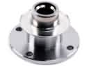 2004 Toyota Sienna CV Joint Companion Flange
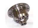 2004 Toyota Sienna Differential
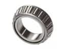 2004 Toyota Sienna Differential Bearing
 2004 Toyota Sienna Differential Seal
 2004 Toyota Sienna Pinion Bearing
 2004 Toyota Sienna Pinion Washer
 2004 Toyota Sienna Transfer Case Bearing
 2004 Toyota Sienna Transfer Case Seal